TSC80C31/80C51
PSEN
XTAL1
Program Store Enable output is the read strobe to external
Program Memory. PSEN is activated twice each machine
cycle during fetches from external Program Memory.
(However, when executing out of external Program
Memory, two activations of PSEN are skipped during
Input to the inverting amplifier that forms the oscillator.
Receives the external oscillator signal when an external
oscillator is used.
each access to external Data Memory). PSEN is not XTAL2
activated during fetches from internal Program Memory.
PSEN can sink or source 8 LS TTL inputs. It can drive
CMOS inputs without an external pullup.
Output of the inverting amplifier that forms the oscillator.
This pin should be floated when an external oscillator is
used.
EA
When EA is held high, the CPU executes out of internal
Program Memory (unless the Program Counter exceeds
3 FFFH). When EA is held low, the CPU executes only out
of external Program Memory. EA must not be floated.
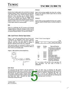
Idle And Power Down Operation
Figure 3. shows the internal Idle and Power Down clock
configuration. As illustrated, Power Down operation
stops the oscillator. Idle mode operation allows the
interrupt, serial port, and timer blocks to continue to
function, while the clock to the CPU is gated off.
PCON : Power Control Register
(MSB)
SMOD
(LSB)
IDL
–
–
–
GF1
GF0
PD
These special modes are activated by software via the
Special Function Register, PCON. Its hardware address is
87H. PCON is not bit addressable.
Symbol
Position
Name and Function
SMOD
PCON.7
Double Baud rate bit. When set to
a 1, the baud rate is doubled when
the serial port is being used in
either modes 1, 2 or 3.
Figure 3. Idle and Power Down Hardware.
–
–
–
GF1
GF0
PD
PCON.6
PCON.5
PCON.4
PCON.3
PCON.2
PCON.1
(Reserved)
(Reserved)
(Reserved)
General-purpose flag bit.
General-purpose flag bit.
Power Down bit. Setting this bit
activates power down operation.
Idle mode bit. Setting this bit
activates idle mode operation.
IDL
PCON.0
If 1’s are written to PD and IDL at the same time. PD
takes, precedence. The reset value of PCON is
(000X0000).
Idle Mode
The instruction that sets PCON.0 is the last instruction There are three ways to terminate the Idle mode.
executed before the Idle mode is activated. Once in the Activation of any enabled interrupt will cause PCON.0 to
Idle mode the CPU status is preserved in its entirety : the be cleared by hardware, terminating Idle mode. The
Stack Pointer, Program Counter, Program Status Word, interrupt is serviced, and following RETI, the next
Accumulator, RAM and all other registers maintain their instruction to be executed will be the one following the
data during idle. Table 1 describes the status of the instruction that wrote 1 to PCON.0.
external pins during Idle mode.
MATRA MHS
5
Rev. E (14 Jan.97)

 TEMIC [ TEMIC SEMICONDUCTORS ]