AN1005
Application Notes
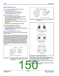
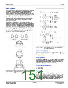
Reflow Soldering Zones
0.079
(2.0)
0.079
(2.0)
0.079
(2.0)
Zone 1: Initial Pre-heating Stage (25 °C to 150 °C)
•
•
•
Excess solvent is driven off.
PCB and Components are gradually heated up.
Temperature gradient shall be <2.5 °C/Sec.
0.040
(1.0)
0.030
(0.76)
0.110
(2.8)
Zone 2: Soak Stage (150 °C to 180 °C)
Pad Outline
•
•
•
•
Flux components start activation and begin to reduce the
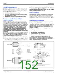
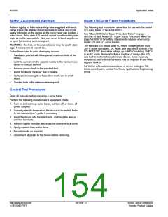
Dimensions are in inches (and millimeters).
oxides on component leads and PCB pads.
PCB components are brought nearer to the temperature at
which solder bonding can occur.
Soak allows different mass components to reach the same
temperature.
Figure AN1005.4
Modified DO-214 Compak — Three-leaded Surface
Mount Package
Activated flux keeps metal surfaces from re-oxidizing.
Zone 3: Reflow Stage (180 °C to 235 °C)
•
•
Paste is brought to the alloy’s melting point.
Activated flux reduces surface tension at the metal interface so
metallurgical bonding occurs.
Zone 4: Cool-down Stage (180 °C to 25 °C)
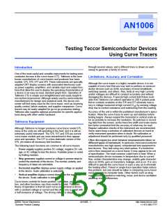
1. Screen print solder paste
(or flux)
Assembly is cooled evenly so thermal shock to the components
or PCB is reduced.
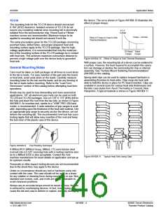
The surface tension of the liquid solder tends to draw the leads of
the device towards the center of the soldering area and so has a
correcting effect on slight mispositionings. However, if the layout
is not optimized, the same effect can result in undesirable shifts,
particularly if the soldering areas on the substrate and the com-
ponents are not concentrically arranged. This problem can be
solved by using a standard contact pattern which leaves suffi-
cient scope for the self-positioning effect (Figure AN1005.3 and
Figure AN1005.4) Figure AN1005.5 shows the reflow soldering
procedure.
2. Place component
(allow flux to dry)
0.079
Pad Outline
(2.0)
0.110
(2.8)
3. Reflow solder
0.079
(2.0)
Dimensions are in inches (and millimeters).
Figure AN1005.5
Reflow Soldering Procedure
After the solder is set and cooled, visually inspect the connec-
tions and, where necessary, correct with a soldering iron. Finally,
the remnants of the flux must be removed carefully.
Use vapor degrease with an azeotrope solvent or equivalent to
remove flux. Allow to dry.
Figure AN1005.3
Minimum Required Dimensions of Metal Connection
of Typical DO-214 Pads on Hybrid Thick- and Thin-
film Substrates
After the drying procedure is complete, the assembly is ready for
testing and/or further processing.
http://www.teccor.com
+1 972-580-7777
AN1005 - 2
©2002 Teccor Electronics
Thyristor Product Catalog

 TECCOR [ TECCOR ELECTRONICS ]