Application Notes
AN1004
Use a clean pre-tinned iron, and solder the joint as quickly as
Soldering Of Leads
possible. Avoid overheating the joint or bringing the iron or solder
into contact with other leads that are not heat sinked.
A prime consideration in soldering leads is the soldering of
device leads into PC boards, heat sinks, and so on. Significant
damage can be done to the device through improper soldering. In
any soldering process, do not exceed the data sheet lead solder
temperature of +230 °C for 10 seconds, maximum, ≥1/16" from
the case.
Wave Solder
Wave soldering is one of the most efficient methods of soldering
large numbers of PC boards quickly and effectively. Guidelines
for soldering by this method are supplied by equipment manufac-
turers. The boards should be pre-heated to avoid thermal shock
to semiconductor components, and the time-temperature cycle in
the solder wave should be regulated to avoid heating the device
beyond the recommended temperature rating. A mildly activated
resin flux is recommended. Figure AN1004.12 shows typical heat
and time conditions.
This application note presents details about the following three
types of soldering:
•
•
•
Hand soldering
Wave soldering
Dip soldering
Hand Soldering
This method is mostly used in prototype breadboarding applica-
tions and production of small modules. It has the greatest poten-
tial for misuse. The following recommendations apply to Teccor
TO-92, TO-202, TO-220, and TO-218 packages.
Select a small- to medium-duty electric soldering iron of 25 W to
45 W designed for electrical assembly application. Tip tempera-
ture should be rated from 600 °F to 800 °F (300 °C to 425 °C).
The iron should have sufficient heat capacity to heat the joint
quickly and efficiently in order to minimize contact time to the
part. Pencil tip probes work very well. Neither heavy-duty electri-
cal irons of greater than 45 W nor flame-heated irons and large
heavy tips are recommended, as the tip temperatures are far too
high and uncontrollable and can easily exceed the time-tempera-
ture limit of the part.
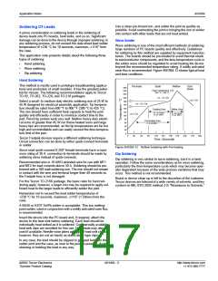
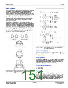
Pre-heat
Soak
Reflow
Cool
260
240
220
Down
Peak Temperature
220 C - 245
C
˚
˚
200
180
160
140
120
100
80
1.3 - 1.6 C/s
˚
<2.5 C/s
˚
0.5 - 0.6 C/s
˚
Soaking Zone
Reflow Zone
60 - 90 s typical
( 2 min. MAX )
30 - 60 s typical
( 2 min. MAX )
<2.5 C/s
˚
Pre-heating Zone
( 2-4 min MAX )
60
40
20
0
0
30
60
90
120
150
180
210
240
270
300
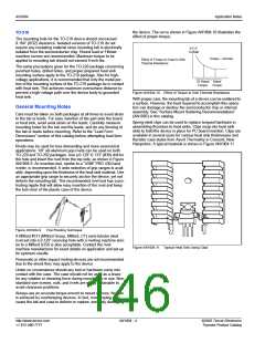
Teccor Fastpak devices require a different soldering technique.
Circuit connection can be done by either quick-connect terminals
or solder.
Since most quick-connect 0.250” female terminals have a maxi-
mum rating of 30 A, connection to terminals should be made by
soldering wires instead of quick-connects.
Recommended wire is 10 AWG stranded wire for use with MT1
and MT2 for load currents above 30 A. Soldering should be per-
formed with a 100-watt soldering iron. The iron should not remain
in contact with the wire and terminal longer than 40 seconds so
the Fastpak triac is not damaged.
For the Teccor TO-218X package, the basic rules for hand sol-
dering apply; however, a larger iron may be required to apply suf-
ficient heat to the larger leads to efficiently solder the joint.
Time (Seconds)
Figure AN1004.12 Reflow Soldering with Pre-heating
Dip Soldering
Dip soldering is very similar to wave soldering, but it is a hand
operation. Follow the same considerations as for wave soldering,
particularly the time-temperature cycle which may become oper-
ator dependent because of the wide process variations that may
occur. This method is not recommended.
Board or device clean-up is left to the discretion of the customer.
Teccor devices are tolerant of a wide variety of solvents, and they
conform to MIL-STD 202E method 215 “Resistance to Solvents.”
Remember not to exceed the lead solder temperatures of
+230 °C for 10 seconds, maximum, ≥1/16" (1.59mm) from the
case.
A 60/40 or 63/37 Sn/Pb solder is acceptable. This low melting-
point solder, used in conjunction with a mildly activated rosin flux,
is recommended.
Insert the device into the PC board and, if required, attach the
device to the heat sink before soldering. Each lead should be
individually heat sinked as it is soldered. Commercially available
heat sink clips are excellent for this use. Hemostats may also be
used if available. Needle-nose pliers are a good heat sink choice;
however, they are not as handy as stand-alone type clips.
In any case, the lead should be clipped or grasped between the
solder joint and the case, as near to the joint as possible. Avoid
straining or twisting the lead in any way.
©2002 Teccor Electronics
Thyristor Product Catalog
AN1004 - 5
http://www.teccor.com
+1 972-580-7777

 TECCOR [ TECCOR ELECTRONICS ]