AN1004
Application Notes
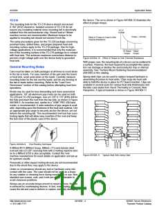
the device. The curve shown in Figure AN1004.10 illustrates the
effect of proper torque.
TO-218
The mounting hole for the TO-218 device should not exceed
0.164” (8/32) clearance. Isolated versions of TO-218 do not
require any insulating material since mounting tab is electrically
isolated from the semiconductor chip. Round lead or Fillister
machine screws are recommended. Maximum torque to be
applied to mounting tab should not exceed 8 inch-lbs.
θ C-S
˚C/Watt
Torque – inch-lbs
Effect of Torque on Case to Sink
Thermal Resistance
The same precautions given for the TO-220 package concerning
punched holes, drilled holes, and proper prepared heat sink
mounting surface apply to the TO-218 package. Also for high-
voltage applications, it is recommended that only the metal por-
tion of the mounting surface of the TO-218 package be in contact
with heat sink. This achieves maximum oversurface distance to
prevent a high-voltage path over the device body to grounded
heat sink.
1/2 Rated Rated
Torque Torque
Figure AN1004.10 Effect of Torque to Sink Thermal Resistance
With proper care, the mounting tab of a device can be soldered to
a surface. However, the heat required to accomplish this opera-
tion can damage or destroy the semiconductor chip or internal
assembly. See “Surface Mount Soldering Recommendations”
(AN1005) in this catalog.
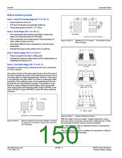
Spring-steel clips can be used to replace torqued hardware in
assembling thyristors to heat sinks. Clips snap into heat sink
slots to hold the device in place for PC board insertion. Clips are
available in several sizes for various heat sink thicknesses and
thyristor case styles from Aavid Thermalloy in Concord, New
Hampshire. A typical heatsink is shown in Figure AN1004.11
General Mounting Notes
Care must be taken on both packages at all times to avoid strain
to the tab or leads. For easy insertion of the part onto the board
or heat sink, avoid axial strain on the leads. Carefully measure
mounting holes for the tab and the leads, and do any forming of
the tab or leads before mounting. Refer to the “Lead Form
Dimensions” section of this catalog before attempting lead form
operations.
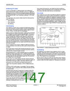
Rivets may be used for less demanding and more economical
applications. 1/8" all-aluminum pop rivets can be used on both
TO-220 and TO-202 packages. Use a 0.129”-0.133” (#30) drill for
the hole and insert the rivet from the top side, as shown in Figure
AN1004.9. An insertion tool, similar to a “USM” PRG 430 hand
riveter, is recommended. A wide selection of grip ranges is avail-
able, depending upon the thickness of the heat sink material. Use
an appropriate grip range to securely anchor the device, yet not
deform the mounting tab. The recommended rivet tool has a pro-
truding nipple that will allow easy insertion of the rivet and keep
the tool clear of the plastic case of the device.
Figure AN1004.9
Pop Riveting Technique
A Milford #511 (Milford Group, Milford, CT) semi-tubular steel
rivet set into a 0.129" receiving hole with a riveting machine simi-
lar to a Milford S256 is also acceptable. Contact the rivet
machine manufacturer for exact details on application and set-up
for optimum results.
Figure AN1004.11 Typical Heat Sink Using Clips
Pneumatic or other impact riveting devices are not recommended
due to the shock they may apply to the device.
Under no circumstance should any tool or hardware come into
contact with the case. The case should not be used as a brace
for any rotation or shearing force during mounting or in use. Non-
standard size screws, nuts, and rivets are easily obtainable to
avoid clearance problems.
Always use an accurate torque wrench to mount devices. No gain
is achieved by overtorquing devices. In fact, overtorquing may
cause the tab and case to deform or rupture, seriously damaging
http://www.teccor.com
+1 972-580-7777
AN1004 - 4
©2002 Teccor Electronics
Thyristor Product Catalog

 TECCOR [ TECCOR ELECTRONICS ]