AN1005
5AN1005
Surface Mount Soldering Recommendations
With the components in position, the substrate is heated to a
point where the solder begins to flow. This can be done on a
Introduction
The most important consideration in reliability is achieving a good
solder bond between surface mount device (SMD) and substrate
since the solder provides the thermal path from the chip. A good
bond is less subject to thermal fatiguing and will result in
improved device reliability.
The most economic method of soldering is a process in which all
different components are soldered simultaneously, such as
DO-214, Compak, TO-252 devices, capacitors, and resistors.
heating plate, on a conveyor belt running through an infrared tun-
nel, or by using vapor phase soldering.
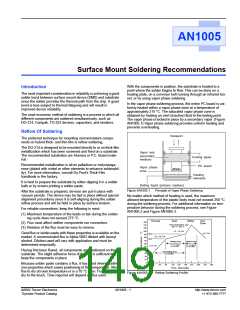
In the vapor phase soldering process, the entire PC board is uni-
formly heated within a vapor phase zone at a temperature of
approximately 215 °C. The saturated vapor phase zone is
obtained by heating an inert (inactive) fluid to the boiling point.
The vapor phase is locked in place by a secondary vapor. (Figure
AN1005.1) Vapor phase soldering provides uniform heating and
prevents overheating.
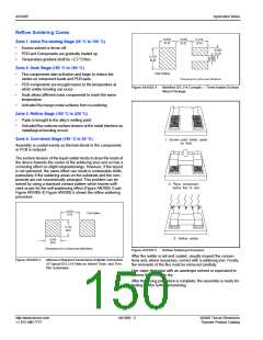
Reflow Of Soldering
Transport
The preferred technique for mounting microminiature compo-
nents on hybrid thick- and thin-film is reflow soldering.
The DO-214 is designed to be mounted directly to or on thick-film
metallization which has been screened and fired on a substrate.
The recommended substrates are Alumina or P.C. Board mate-
rial.
Vapor lock
(secondary
medium)
Cooling pipes
Recommended metallization is silver palladium or molymanga-
nese (plated with nickel or other elements to enhance solderabil-
ity). For more information, consult Du Pont's Thick-Film
handbook or the factory.
PC board
Vapor phase
zone
Heating
elements
It is best to prepare the substrate by either dipping it in a solder
bath or by screen printing a solder paste.
After the substrate is prepared, devices are put in place with
vacuum pencils. The device may be laid in place without special
alignment procedures since it is self-aligning during the solder
reflow process and will be held in place by surface tension.
Boiling liquid (primary medium)
Figure AN1005.1
Principle of Vapor Phase Soldering
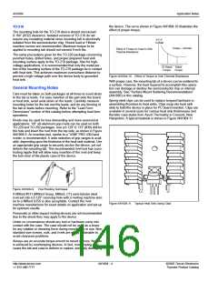
No matter which method of heating is used, the maximum
allowed temperature of the plastic body must not exceed 250 °C
during the soldering process. For additional information on tem-
perature behavior during the soldering process, see Figure
AN1005.2 and Figure AN1005.3.
For reliable connections, keep the following in mind:
(1) Maximum temperature of the leads or tab during the solder-
ing cycle does not exceed 275 °C.
Pre-heat
Soak
Reflow
Cool
260
240
220
(2) Flux must affect neither components nor connectors.
(3) Residue of the flux must be easy to remove.
Good flux or solder paste with these properties is available on the
market. A recommended flux is Alpha 5003 diluted with benzyl
alcohol. Dilution used will vary with application and must be
determined empirically.
Having first been fluxed, all components are positioned on the
substrate. The slight adhesive force of the flux is sufficient to
keep the components in place.
Because solder paste contains a flux, it has good inherent adhe-
sive properties which eases positioning of the components. Allow
flux to dry at room temperature or in a 70 °C oven. Flux should be
dry to the touch. Time required will depend on flux used.
Down
Peak Temperature
220 C - 245
˚
C
˚
200
180
160
140
120
100
80
1.3 - 1.6 C/s
˚
<2.5 C/s
˚
0.5 - 0.6 C/s
˚
Soaking Zone
Reflow Zone
60 - 90 s typical
( 2 min. MAX )
30 - 60 s typical
( 2 min. MAX )
<2.5 C/s
˚
Pre-heating Zone
( 2-4 min MAX )
60
40
20
0
0
30
60
90
120
150
180
210
240
270
300
Time (Seconds)
Figure AN1005.2
Reflow Soldering Profile
©2002 Teccor Electronics
Thyristor Product Catalog
AN1005 - 1
http://www.teccor.com
+1 972-580-7777

 TECCOR [ TECCOR ELECTRONICS ]