Application Notes
AN1001
When voltage is impressed suddenly across a PN junction, a
charging current flows, equal to:
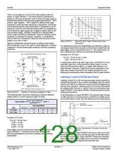
modes are Quadrants II and III where the gate has a negative
polarity supply with an AC main terminal supply. Typically, Quad-
rant II is approximately equal in gate sensitivity to Quadrant I;
however, latching current sensitivity in Quadrant II is lowest.
Therefore, it is difficult for triacs to latch on in Quadrant II when
the main terminal current supply is very low in value.
dv
ꢀ
.
------
dt
i = C
0
dv
------
ꢀ
.
When C
becomes greater or equal to thyristor IGT,
Special consideration should be given to gating circuit design
when Quadrants I and IV are used in actual application, because
Quadrant IV has the lowest gate sensitivity of all four operating
quadrants.
0
dt
the thyristor switches on. Normally, this type of turn-on does not
damage the device, providing the surge current is limited.
Generally, thyristor application circuits are designed with static
dv/dt snubber networks if fast-rising voltages are anticipated.
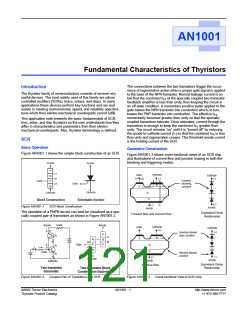
General Terminology
Voltage Breakover Turn-on
This method is used to switch on sidacs and diacs. However,
exceeding voltage breakover of SCRs and triacs is definitely not
recommended as a turn-on method.
In the case of SCRs and triacs, leakage current increases until it
exceeds the gate current required to turn on these gated thyris-
tors in a small localized point. When turn-on occurs by this
method, localized heating in a small area may melt the silicon or
damage the device if di/dt of the increasing current is not suffi-
ciently limited.
Diacs used in typical phase control circuits are basically pro-
tected against excessive current at breakover as long as the fir-
ing capacitor is not excessively large. When diacs are used in a
zener function, current limiting is necessary.
The following definitions of the most widely-used thyristor terms,
symbols, and definitions conform to existing EIA-JEDEC stan-
dards:
Breakover Point – Any point on the principal voltage-current
characteristic for which the differential resistance is zero and
where the principal voltage reaches a maximum value
Principal Current – Generic term for the current through the col-
lector junction (the current through main terminal 1 and main ter-
minal 2 of a triac or anode and cathode of an SCR)
Principal Voltage – Voltage between the main terminals:
(1) In the case of reverse blocking thyristors, the principal volt-
age is called positive when the anode potential is higher than
the cathode potential and negative when the anode potential
is lower than the cathode potential.
(2) For bidirectional thyristors, the principal voltage is called
positive when the potential of main terminal 2 is higher than
the potential of main terminal 1.
Sidacs are typically pulse-firing, high-voltage transformers and
are current limited by the transformer primary. The sidac should
be operated so peak current amplitude, current duration, and
di/dt limits are not exceeded.
Off State – Condition of the thyristor corresponding to the high-
resistance, low-current portion of the principal voltage-current
characteristic between the origin and the breakover point(s) in
the switching quadrant(s)
Triac Gating Modes Of Operation
Triacs can be gated in four basic gating modes as shown in
Figure AN1001.17.
On State – Condition of the thyristor corresponding to the low-
resistance, low-voltage portion of the principal voltage-current
characteristic in the switching quadrant(s).
ALL POLARITIES ARE REFERENCED TO MT1
MT2 POSITIVE
(Positive Half Cycle)
MT2
MT2
+
Specific Terminology
Average Gate Power Dissipation [PG(AV)] – Value of gate power
which may be dissipated between the gate and main terminal 1
(or cathode) averaged over a full cycle
(-)
I
GATE
(+)
I
GT
GT
GATE
MT1
MT1
REF
MT2
REF
MT2
QII QI
QIII QIV
Breakover Current (IBO) – Principal current at the breakover
I
-
+ I
GT
GT
point
Breakover Voltage (VBO) – Principal voltage at the breakover
(-)
I
GATE
(+)
I
GATE
GT
GT
point
MT1
REF
MT1
REF
Circuit-commutated Turn-off Time (tq) – Time interval between
the instant when the principal current has decreased to zero after
external switching of the principal voltage circuit and the instant
when the thyristor is capable of supporting a specified principal
voltage without turning on
-
MT2 NEGATIVE
(Negative Half Cycle)
NOTE: Alternistors will not operate in Q IV
Figure AN1001.17
Gating Modes
Critical Rate-of-rise of Commutation Voltage of a Triac
(Commutating dv/dt) – Minimum value of the rate-of-rise of prin-
cipal voltage which will cause switching from the off state to the
on state immediately following on-state current conduction in the
opposite quadrant
The most common quadrants for triac gating-on are Quadrants I
and III, where the gate supply is synchronized with the main ter-
minal supply (gate positive — MT2 positive, gate negative —
MT2 negative). Gate sensitivity of triacs is most optimum in
Quadrants I and III due to the inherent thyristor chip construction.
If Quadrants I and III cannot be used, the next best operating
©2002 Teccor Electronics
Thyristor Product Catalog
AN1001 - 5
http://www.teccor.com
+1 972-580-7777

 TECCOR [ TECCOR ELECTRONICS ]