Application Notes
AN1001
Sidac
Diac
Basic Operation
Basic Operation
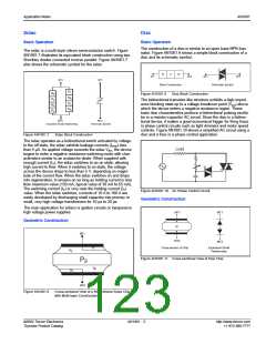
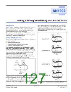
The construction of a diac is similar to an open base NPN tran-
sistor. Figure AN1001.9 shows a simple block construction of a
diac and its schematic symbol.
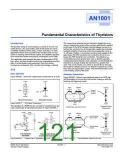
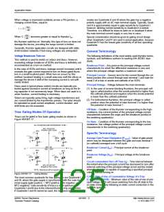
The sidac is a multi-layer silicon semiconductor switch. Figure
AN1001.7 illustrates its equivalent block construction using two
Shockley diodes connected inverse parallel. Figure AN1001.7
also shows the schematic symbol for the sidac.
N
N
P
MT1
MT2
MT2
MT1
MT1
MT1
Block Construction
Schematic Symbol
P
1
N2
P3
N4
P5
Figure AN1001.9
Diac Block Construction
N2
P3
N4
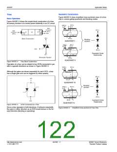
The bidirectional transistor-like structure exhibits a high-imped-
ance blocking state up to a voltage breakover point (VBO) above
which the device enters a negative-resistance region. These
basic diac characteristics produce a bidirectional pulsing oscilla-
tor in a resistor-capacitor AC circuit. Since the diac is a bidirec-
tional device, it makes a good economical trigger for firing triacs
in phase control circuits such as light dimmers and motor speed
controls. Figure AN1001.10 shows a simplified AC circuit using a
diac and a triac in a phase control application.
MT2
Equivalent Diode Relationship
MT2
Schematic Symbol
Figure AN1001.7
Sidac Block Construction
The sidac operates as a bidirectional switch activated by voltage.
In the off state, the sidac exhibits leakage currents (IDRM) less
than 5 µA. As applied voltage exceeds the sidac VBO, the device
begins to enter a negative resistance switching mode with char-
acteristics similar to an avalanche diode. When supplied with
enough current (IS), the sidac switches to an on state, allowing
high current to flow. When it switches to on state, the voltage
across the device drops to less than 5 V, depending on magni-
tude of the current flow. When the sidac switches on and drops
into regeneration, it remains on as long as holding current is less
than maximum value (150 mA, typical value of 30 mA to 65 mA).
The switching current (IS) is very near the holding current (IH)
value. When the sidac switches, currents of 10 A to 100 A are
easily developed by discharging small capacitor into primary or
small, very high-voltage transformers for 10 µs to 20 µs.
Load
Figure AN1001.10 AC Phase Control Circuit
Geometric Construction
The main application for sidacs is ignition circuits or inexpensive
high voltage power supplies.
MT1
MT1
Geometric Construction
N
P
N
MT1
MT2
MT2
Cross-section of Chip
Equivalent Diode
Relationship
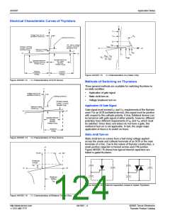
P1
N2
Figure AN1001.11 Cross-sectional View of Diac Chip
P3
N4
P5
MT2
Figure AN1001.8
Cross-sectional View of a Bidirectional Sidac Chip
with Multi-layer Construction
©2002 Teccor Electronics
Thyristor Product Catalog
AN1001 - 3
http://www.teccor.com
+1 972-580-7777

 TECCOR [ TECCOR ELECTRONICS ]