AN1001
Application Notes
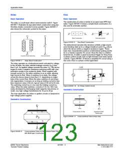
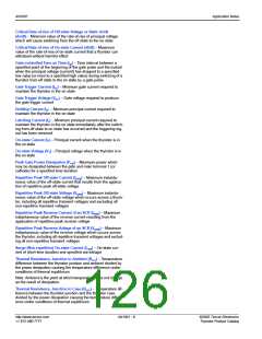
Geometric Construction
Triac
Figure AN1001.6 show simplified cross-sectional views of a triac
Basic Operation
chip in various gating quadrants and blocking modes.
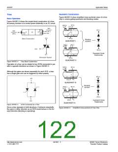
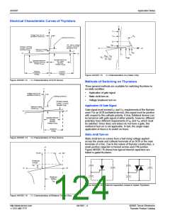
Figure AN1001.4 shows the simple block construction of a triac.
Its primary function is to control power bilaterally in an AC circuit.
MT1(-)
P
GATE(+)
I
GT
Main
N
N
Terminal 1
(MT1)
MT1(-)
N
Main
Terminal 2
(MT2)
N
P
P
N
Gate
N
N
P
I
N
T
MT2
MT2(+)
Block Construction
Blocking
Junction
QUADRANT I
MT1(-)
P
GATE(-)
GT
I
N
N
Gate
MT2(+)
N
Equivalent Diode
Relationship
P
MT1
N
Schematic Symbol
MT2(+)
QUADRANT II
Figure AN1001.4
Triac Block Construction
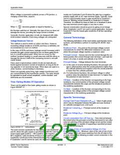
Operation of a triac can be related to two SCRs connected in par-
allel in opposite directions as shown in Figure AN1001.5.
GATE(-)
MT1(+)
P
I
GT
N
N
Although the gates are shown separately for each SCR, a triac
has a single gate and can be triggered by either polarity.
N
MT1(+)
P
N
MT1
I
MT2(-)
T
QUADRANT III
Blocking
Junction
MT1(+)
P
GATE(+)
I
GT
N
N
N
P
N
MT2(-)
I
MT2(-)
T
Equivalent Diode
Relationship
MT2
QUADRANT IV
Figure AN1001.5
SCRs Connected as a Triac
Since a triac operates in both directions, it behaves essentially
the same in either direction as an SCR would behave in the for-
ward direction (blocking or operating).
Figure AN1001.6
Simplified Cross-sectional of Triac Chip
http://www.teccor.com
+1 972-580-7777
AN1001 - 2
©2002 Teccor Electronics
Thyristor Product Catalog

 TECCOR [ TECCOR ELECTRONICS ]