AN1001
Application Notes
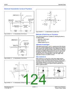
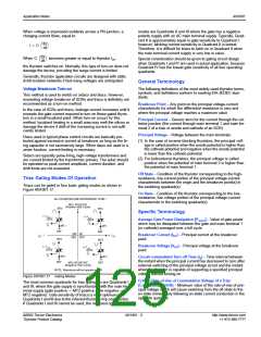
Electrical Characteristic Curves of Thyristors
+I
+I
IT
Voltage Drop (VT) at
Specified Current (iT)
IH
RS
Latching Current (IL)
IS
Off - State Leakage
Current - (IDRM) at
Specified VDRM
IBO
IDRM
Reverse Leakage
Current - (IRRM) at
Specified VRRM
-V
+V
Minimum Holding
Current (IH
)
VBO
VS
-V
+V
VT
(VBO - VS)
=
RS
VDRM
(IS - IBO
)
Specified Minimum
Off - State
Blocking
Specified Minimum
Reverse Blocking
Voltage (VRRM
)
Voltage (VDRM
)
-I
Reverse
Breakdown
Voltage
Forward
Breakover
Voltage
Figure AN1001.15
V-I Characteristics of a Sidac Chip
-I
Figure AN1001.12
V-I Characteristics of SCR Device
Methods of Switching on Thyristors
Three general methods are available for switching thyristors to
+I
on-state condition:
•
•
•
Application of gate signal
Static dv/dt turn-on
Voltage breakover turn-on
Voltage Drop (VT) at
Specified Current (iT
)
Latching Current (IL)
Off-state Leakage
Current – (IDRM
) at
Specified VDRM
Application Of Gate Signal
Minimum Holding
Current (IH
)
Gate signal must exceed IGT and VGT requirements of the thyristor
used. For an SCR (unilateral device), this signal must be positive
with respect to the cathode polarity. A triac (bilateral device) can
be turned on with gate signal of either polarity; however, different
polarities have different requirements of IGT and VGT which must
be satisfied. Since diacs and sidacs do not have a gate, this
method of turn-on is not applicable. In fact, the single major
application of diacs is to switch on triacs.
-V
+V
Specified Minimum
Off-state
Blocking
Voltage (VDRM
)
Breakover
Voltage
-I
Static dv/dt Turn-on
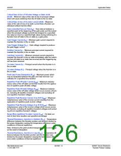
Figure AN1001.13
V-I Characteristics of Triac Device
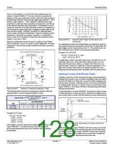
Static dv/dt turn-on comes from a fast-rising voltage applied
across the anode and cathode terminals of an SCR or the main
terminals of a triac. Due to the nature of thyristor construction, a
small junction capacitor is formed across each PN junction.
Figure AN1001.16 shows how typical internal capacitors are
linked in gated thyristors.
+I
10 mA
∆V
Breakover
Current
I
BO
-V
+V
Breakover
Voltage
V
BO
Figure AN1001.16 Internal Capacitors Linked in Gated Thyristors
-I
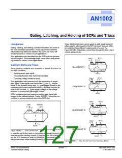
Figure AN1001.14
V-I Characteristics of Bilateral Trigger Diac
http://www.teccor.com
+1 972-580-7777
AN1001 - 4
©2002 Teccor Electronics
Thyristor Product Catalog

 TECCOR [ TECCOR ELECTRONICS ]