AN1002
AN1002
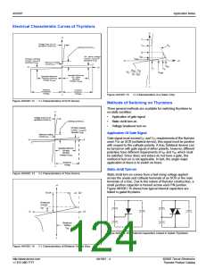
Gating, Latching, and Holding of SCRs and Triacs
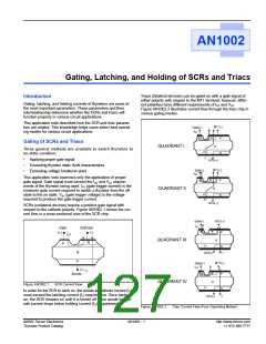
Triacs (bilateral devices) can be gated on with a gate signal of
either polarity with respect to the MT1 terminal; however, differ-
Introduction
Gating, latching, and holding currents of thyristors are some of
the most important parameters. These parameters and their
interrelationship determine whether the SCRs and triacs will
function properly in various circuit applications.
ent polarities have different requirements of IGT and VGT.
Figure AN1002.2 illustrates current flow through the triac chip in
various gating modes.
This application note describes how the SCR and triac parame-
ters are related. This knowledge helps users select best operat-
ing modes for various circuit applications.
MT1(-)
Gate(+)
I
GT
N
N
P
N
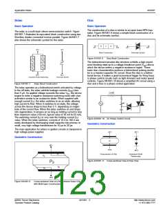
Gating of SCRs and Triacs
N
QUADRANT I
Three general methods are available to switch thyristors to
P
on-state condition:
I
T
•
•
•
Applying proper gate signal
Exceeding thyristor static dv/dt characteristics
Exceeding voltage breakover point
MT2(+)
MT1(-)
Gate(-)
GT
I
This application note examines only the application of proper
gate signal. Gate signal must exceed the IGT and VGT require-
ments of the thyristor being used. IGT (gate trigger current) is the
minimum gate current required to switch a thyristor from the off
state to the on state. VGT (gate trigger voltage) is the voltage
required to produce the gate trigger current.
SCRs (unilateral devices) require a positive gate signal with
respect to the cathode polarity. Figure AN1002.1 shows the cur-
rent flow in a cross-sectional view of the SCR chip.
N
N
P
N
QUADRANT II
P
N
MT2(+)
Gate(-)
MT1(+)
I
GT
Gate
(+)
Cathode
(-)
N
N
P
IGT
N
QUADRANT III
QUADRANT IV
N
P
P
N
I
N
P
MT2(-)
T
MT1(+)
Gate(+)
I
GT
(+)
IT
N
N
P
Anode
N
Figure AN1002.1
SCR Current Flow
P
N
In order for the SCR to latch on, the anode-to-cathode current (IT)
must exceed the latching current (IL) requirement. Once latched
on, the SCR remains on until it is turned off when anode-to-cath-
ode current drops below holding current (IH) requirement.
I
MT2(-)
T
Figure AN1002.2
Triac Current Flow (Four Operating Modes)
©2002 Teccor Electronics
Thyristor Product Catalog
AN1002 - 1
http://www.teccor.com
+1 972-580-7777

 TECCOR [ TECCOR ELECTRONICS ]