Document Number: PS-MPU-6500A-01
Revision: 1.1
Release Date: 03/05/2014
MPU-6500 Product Specification
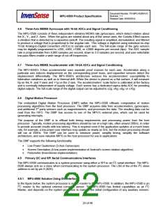
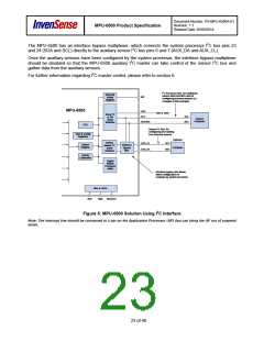
The MPU-6500 has an interface bypass multiplexer, which connects the system processor I2C bus pins 23
and 24 (SDA and SCL) directly to the auxiliary sensor I2C bus pins 6 and 7 (AUX_DA and AUX_CL).
Once the auxiliary sensors have been configured by the system processor, the interface bypass multiplexer
should be disabled so that the MPU-6500 auxiliary I2C master can take control of the sensor I2C bus and
gather data from the auxiliary sensors.
For further information regarding I2C master control, please refer to section 6.
I2C Processor Bus: for reading all
sensor data from MPU and for
configuring external sensors (i.e.
compass in this example)
Interrupt
Status
Register
INT
MPU-6500
AD0
SCL
VDD or GND
Slave I2C
or SPI
SCL
SDA
System
Processor
Serial
Interface
SDA/SDI
FIFO
Sensor I2C Bus: for
configuring and reading
from external sensors
User & Config
Registers
Optional
Sensor
Master I2C
Serial
AUX_CL
AUX_DA
SCL
SDA
Sensor
Register
Interface
Bypass
Mux
Compass
Interface
Factory
Calibration
Digital
Motion
Processor
(DMP)
Interface bypass mux allows
direct configuration of
compass by system processor
Bias & LDOs
VDD
GND
REGOUT
Figure 6: MPU-6500 Solution Using I2C Interface
Note: The Interrupt line should be connected to a pin on the Application Processor (AP) that can bring the AP out of suspend
mode.
23 of 40

 TDK [ TDK ELECTRONICS ]