Document Number: PS-MPU-6500A-01
Revision: 1.1
Release Date: 03/05/2014
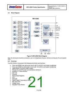
MPU-6500 Product Specification
Auxiliary I2C Bus Modes of Operation:
•
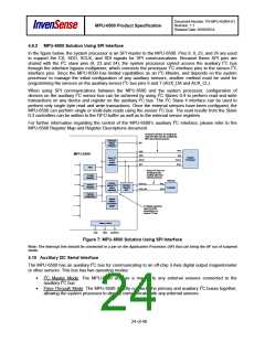
I2C Master Mode: Allows the MPU-6500 to directly access the data registers of external digital
sensors, such as a magnetometer. In this mode, the MPU-6500 directly obtains data from auxiliary
sensors without intervention from the system applications processor.
For example, In I2C Master mode, the MPU-6500 can be configured to perform burst reads, returning
the following data from a magnetometer:
.
.
.
X magnetometer data (2 bytes)
Y magnetometer data (2 bytes)
Z magnetometer data (2 bytes)
The I2C Master can be configured to read up to 24 bytes from up to 4 auxiliary sensors. A fifth sensor
can be configured to work single byte read/write mode.
•
Pass-Through Mode: Allows an external system processor to act as master and directly
communicate to the external sensors connected to the auxiliary I2C bus pins (AUX_DA and
AUX_CL). In this mode, the auxiliary I2C bus control logic (3rd party sensor interface block) of the
MPU-6500 is disabled, and the auxiliary I2C pins AUX_DA and AUX_CL (Pins 6 and 7) are
connected to the main I2C bus (Pins 23 and 24) through analog switches internally.
Pass-Through mode is useful for configuring the external sensors, or for keeping the MPU-6500 in a
low-power mode when only the external sensors are used. In this mode the system processor can
still access MPU-6500 data through the I2C interface.
4.11 Self-Test
Please refer to the register map document for more details on self-test.
Self-test allows for the testing of the mechanical and electrical portions of the sensors. The self-test for each
measurement axis can be activated by means of the gyroscope and accelerometer self-test registers
(registers 13 to 16).
When the self-test is activated, the electronics cause the sensors to be actuated and produce an output
signal. The output signal is used to observe the self-test response.
The self-test response is defined as follows:
Self-test response = Sensor output with self-test enabled – Sensor output without self-test enabled
The self-test response for each gyroscope axis is defined in the gyroscope specification table, while that for
each accelerometer axis is defined in the accelerometer specification table.
When the value of the self-test response is within the specified min/max limits of the product specification,
the part has passed self-test. When the self-test response exceeds the min/max values, the part is deemed
to have failed self-test. It is recommended to use InvenSense MotionApps software for executing self-test.
4.12 Clocking
The MPU-6500 has a flexible clocking scheme, allowing a variety of internal clock sources to be used for the
internal synchronous circuitry. This synchronous circuitry includes the signal conditioning and ADCs, the
DMP, and various control circuits and registers. An on-chip PLL provides flexibility in the allowable inputs for
generating this clock.
Allowable internal sources for generating the internal clock are:
•
•
An internal relaxation oscillator
Any of the X, Y, or Z gyros (MEMS oscillators with a variation of ±1% over temperature)
25 of 40

 TDK [ TDK ELECTRONICS ]