ICM-20690
12 REGISTER DESCRIPTIONS
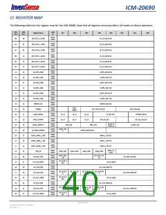
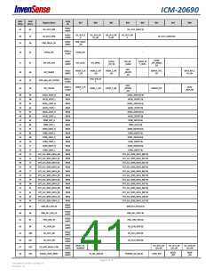
This section describes the function and contents of the registers within the ICM-20690.
Note: The device powers up in Sleep Mode.
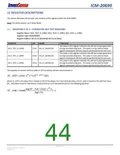
12.1 REGISTERS 0 TO 2 – GYROSCOPE SELF-TEST REGISTERS
Register Name: SELF_TEST_X_GYRO, SELF_TEST_Y_GYRO, SELF_TEST_Z_GYRO
Register Type: READ/WRITE
Register Address: 00, 01, 02 (Decimal); 00, 01, 02 (Hex)
REGISTER
BIT
NAME
FUNCTION
The value in this register indicates the self-test output generated
during manufacturing tests. This value is to be used to check
against subsequent self-test outputs performed by the end user.
The value in this register indicates the self-test output generated
during manufacturing tests. This value is to be used to check
against subsequent self-test outputs performed by the end user.
The value in this register indicates the self-test output generated
during manufacturing tests. This value is to be used to check
against subsequent self-test outputs performed by the end user.
SELF_TEST_X_GYRO
[7:0] XG_ST_DATA[7:0]
[7:0] YG_ST_DATA[7:0]
[7:0] ZG_ST_DATA[7:0]
SELF_TEST_Y_GYRO
SELF_TEST_Z_GYRO
The equation to convert self-test codes in OTP to factory self-test measurement is:
ST _OTP (2620/2FS )*1.01(ST _code1) (lsb)
where ST_OTP is the value that is stored in OTP of the device, FS is the Full Scale value, and ST_code is based on the Self-Test value
(ST_ FAC) determined in InvenSense’s factory final test and calculated based on the following equation:
log(ST _ FAC /(2620/2FS ))
ST _ code round(
) 1
log(1.01)
Page 44 of 76
Document Number: DS-000178
Revision: 1.0

 TDK [ TDK ELECTRONICS ]