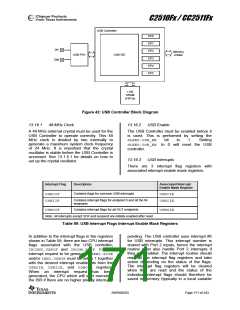
C2510Fx / CC2511Fx
tokens.
A
successful OUT transaction
The USBINDEXregister must have the value of
the endpoint number before the Indexed
Endpoint Registers are accessed (see Table
35 on Page 50).
comprises two or three sequential packets (a
token packet, a data packet, and a handshake
packet18). If more than 32 bytes (maximum
packet size) is to be received, the data must
be split into a number of 32 byte packets
followed by a residual packet. If the number of
bytes to receive is a multiple of 32, the residual
packet will be a zero length data packet, hence
a data packet with payload less than 32 bytes
denotes the end of the transfer.
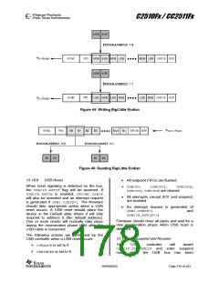
13.16.6.1 FIFO Management
Each endpoint has a certain number of FIFO
memory bytes available for incoming and
outgoing data packets. Table 60 shows the
FIFO size for endpoints 1 - 5. It is the firmware
that is responsible for setting the USBMAXIand
USBMAXO registers correctly for each endpoint
to prevent data from being overwritten.
The USBCS0.OUTPKT_RDY bit will be set and
an EP0 interrupt will be generated when a data
packet has been received. The firmware
should set USBCS0.CLR_OUTPKT_RDY when
the data packet has been unloaded from the
EP0 FIFO. When the last data packet has
been received (packet size less than 32 bytes)
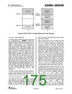
When both the IN and the OUT endpoint of an
endpoint number do not use double buffering,
the sum of USBMAXI and USBMAXO must not
exceed the FIFO size for the endpoint. Figure
43 a) shows how the IN and OUT FIFO
memory for an endpoint is organized with
single buffering. The IN FIFO grows down from
the top of the endpoint memory region while
the OUT FIFO grows up from the bottom of the
endpoint memory region.
firmware
should
also
set
the
USBCS0.DATA_END bit. This will start the
Status stage of the control transfer. The size of
the data packet is kept in the USBCNT0
registers. Note that this value is only valid
when USBCS0.OUTPKT_RDY=1.
EP0 will switch to the IDLE state when the
Status stage has completed. The Status stage
may fail if the DATA1 packet received is not a
zero length data packet or if the
USBCS0.SEND_STALL bit is set to 1. The
USBCS0.SENT_STALL bit will then be
asserted and an EP0 interrupt will be
generated as explained in Section 13.16.5.1.
When the IN or OUT endpoint of an endpoint
number use double buffering, the sum of
USBMAXI and USBMAXO must not exceed half
the FIFO size for the endpoint. Figure 43 b)
illustrates the IN and OUT FIFO memory for an
endpoint that uses double buffering. Notice
that the second OUT buffer starts from the
middle of the memory region and grows
upwards. The second IN buffer also starts from
the middle of the memory region but grows
downwards.
13.16.6 Endpoints 1 – 5
Each endpoint can be used as an IN only, an
OUT only, or IN/OUT. For an IN/OUT endpoint
there are basically two endpoints, an IN
endpoint and an OUT endpoint associated with
the endpoint number. Configuration and
control of IN endpoints is performed through
the USBCSIL and USBCSIH registers. The
USBCSOL and USBCSOH registers are used to
configure and control OUT endpoints. Each IN
and OUT endpoint can be configured as either
To configure an endpoint as IN only, set
USBMAXOto 0 and to configure an endpoint as
OUT only, set USBMAXIto 0.
For unused endpoints, both USBMAXO and
USBMAXIshould be set to 0.
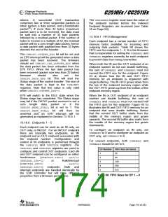
EP Number FIFO Size (in bytes)
1
2
3
4
5
32
Isochronous
(USBCSIH.ISO=1
and/or
Bulk/Interrupt
and/or
64
USBCSOH.ISO=1)
(USBCSIH.ISO=0
USBCSOH.ISO=0)
or
128
256
512
endpoints.
Bulk
and
Interrupt endpoints are handled identically by
the USB controller but will have different
properties from a firmware perspective.
Table 60: FIFO Sizes for EP 1 – 5
SWRS055D
Page 174 of 243

 TAOS [ TEXAS ADVANCED OPTOELECTRONIC SOLUTIONS ]