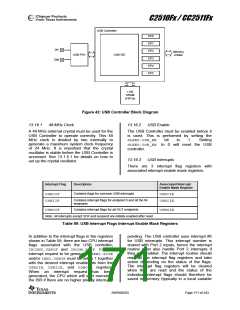
C2510Fx / CC2511Fx
USB Controller
EP0
EP1
DP
EP2
Memory
USB PHY
USB SIE
Arbiter
EP3
DM
EP4
EP5
1 KB
SRAM
(FIFOs)
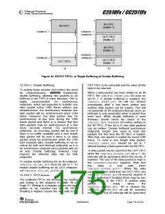
Figure 42: USB Controller Block Diagram
13.16.1
48 MHz Clock
13.16.2
USB Enable
A 48 MHz external crystal must be used for the
USB Controller to operate correctly. This 48
MHz clock is divided by two internally to
generate a maximum system clock frequency
of 24 MHz. It is important that the crystal
oscillator is stable before the USB Controller is
accessed. See 13.1.5.1 for details on how to
set up the crystal oscillator.
The USB Controller must be enabled before it
is used. This is performed by setting the
SLEEP.USB_EN
bit
to
1.
Setting
SLEEP.USB_EN to 0 will reset the USB
controller.
13.16.3
USB Interrupts
There are 3 interrupt flag registers with
associated interrupt enable mask registers.
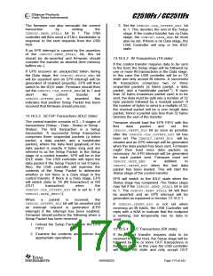
Interrupt Flag
Description
Associated Interrupt
Enable Mask Register
Contains flags for common USB interrupts
USBCIF
USBIIF
USBCIE
USBIIE
Contains interrupt flags for endpoint 0 and all the IN
endpoints
Contains interrupt flags for all OUT endpoints
USBOIF
USBOIE
Note: All interrupts except SOF and suspend are initially enabled after reset
Table 59: USB Interrupt Flags Interrupt Enable Mask Registers
In addition to the interrupt flags in the registers
pending. The USB controller uses interrupt #6
for USB interrupts. This interrupt number is
shared with Port 2 inputs, hence the interrupt
routine must also handle Port 2 interrupts if
they are enabled. The interrupt routine should
read all the interrupt flag registers and take
action depending on the status of the flags.
The interrupt flag registers will be cleared
when they are read and the status of the
individual interrupt flags should therefore be
saved in memory (typically in a local variable
shown in Table 59, there are two CPU interrupt
flags associated with the USB controller;
IRCON2.USBIF and IRCON.P0IF. For an
interrupt request to be generated, IEN1.P0IE
and/or IEN2.USBIEmust be set to 1 together
with the desired interrupt enable bits from the
USBCIE, USBIIE, and USBOIE registers.
When an interrupt request has been
generated, the CPU which will start executing
the ISR if there are no higher priority interrupts
SWRS055D
Page 171 of 243

 TAOS [ TEXAS ADVANCED OPTOELECTRONIC SOLUTIONS ]