C2510Fx / CC2511Fx
on the stack) to allow them to be accessed
multiple times.
13.16.5
Endpoint 0 Interrupts
The following events may generate an EP0
interrupt request:
At the end of the ISR, after the interrupt flags
have been read, the interrupt flags should be
cleared to allow for new USB/P2 interrupts to
be detected. The port 2 interrupt status flags in
the P2IFG register should be cleared prior to
clearing IRCON2.P2IF(see Section 11.5.2).
• A data packet has been received
(USBCS0.OUTPKT_RDY=1)
• A data packet that was loaded into the
EP0 FIFO has been sent to the USB
host (USBCS0.INPKT_RDY should be
set to 1 when a new packet is ready to
be transferred. This bit will be cleared by
HW when the data packet has been
sent)
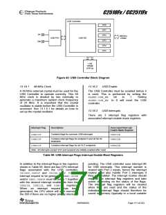
Refer
to
Table 39 and Table 40 for a complete list of
interrupts, and Section 11.5 for more details
about interrupts.
• An IN transaction has been completed
(the interrupt is generated during the
Status stage of the transaction)
13.16.3.1 USB Resume Interrupt
P0_7 does not exist on the CC2511Fx, but the
corresponding interrupt is used for USB
resume interrupt. This means that to be able to
wake up the CC2511Fx from PM1/suspend when
resume signaling has been detected on the
USB bus, IEN1.P0IE must be set to 1
• A
STALL
has
been
sent
(USBCS0.SENT_STALL=1)
• A control transfer ends due to a
premature end of control transfer
(USBCS0.SETUP_END=1)
together
with
PICTL.P0IENH.
PICTL.P0ICONmust be 0 to enable interrupts
on rising edge. The P0 ISR should check the
P0IFG.USB_RESUME, and resume if this bit is
set to 1. If PM1 is entered from within an ISR
due to a suspend interrupt, it is important that
the priority of the P0 interrupt is set higher than
the priority of the interrupt from which PM1
was entered. See Section 13.16.9 for more
details about suspend and resume.
Any of these events will cause the
USBIIF.EP0IF to be asserted regardless of
the status of the EP0 interrupt mask bit
USBIIE.EP0IE. If the EP0 interrupt mask bit
is set to 1, the CPU interrupt flag
IRCON2.USBIF will also be asserted. An
interrupt request is only generated if
IEN2.USBIE and USBIIE.EP0IE are both
set to 1.
13.16.4
Endpoint 0
13.16.5.1 Error Conditions
Endpoint 0 (EP0) is a bi-directional control
endpoint and during the enumeration phase all
communication is performed across this
endpoint. Before the USBADDR register has
been set to a value other than 0, the USB
controller will only be able to communicate
through endpoint 0. Setting the USBADDR
register to a value between 1 and 127 will
bring the USB function out of the Default state
in the enumeration phase and into the Address
state. All configured endpoints will then be
available for the application.
When a protocol error occurs, the USB
controller sends a STALL handshake. The
USBCS0.SENT_STALL bit is asserted and an
interrupt request is generated if the endpoint 0
interrupt is properly enabled. A protocol error
can be any of the following:
• An OUT token is received after
USBCS0.DATA_END has been set to
complete the OUT Data stage (the host
tries to send more data than expected)
• An IN token is received after
USBCS0.DATA_END has been set to
complete the IN Data stage (the host
tries to receive more data than
expected)
The EP0 FIFO is only used as either IN or
OUT and double buffering is not provided for
endpoint 0. The maximum packet size for
endpoint 0 is fixed at 32 bytes.
Endpoint 0 is controlled through the USBCS0
register by setting the USBINDEXregister to 0.
The USBCNT0 register contains the number of
bytes received.
• The USB host tries to send a packet that
exceeds the maximum packet size
during the OUT Data stage
• The size of the DATA1 packet received
during the Status stage is not 0
SWRS055D
Page 172 of 243

 TAOS [ TEXAS ADVANCED OPTOELECTRONIC SOLUTIONS ]