C2510Fx / CC2511Fx
The firmware can also terminate the current
transaction by setting the
USBCS0.SEND_STALL bit to 1. The USB
controller will then send a STALL handshake in
response to the next requests from the USB
host.
3. Set the USBCS0.CLR_OUTPKT_RDY bit
to 1. This denotes the end of the Setup
stage. If the control transfer has no Data
stage, the USBCS0.DATA_END bit must
also be set. If there is no Data stage, the
USB Controller will stay in the IDLE
state.
If an EP0 interrupt is caused by the assertion
of the USBCS0.SENT_STALL bit, this bit
should be de-asserted and firmware should
consider the transfer as aborted (free memory
buffers etc.).
13.16.5.3 IN Transactions (TX state)
If the control transfer requires data to be sent
to the host, the Setup stage will be followed by
one or more IN transactions in the Data stage.
In this case the USB controller will be in TX
state and only accept IN tokens. A successful
IN transaction comprises two or three
sequential packets (a token packet, a data
packet, and a handshake packet17). If more
than 32 bytes (maximum packet size) is to be
sent, the data must be split into a number of 32
byte packets followed by a residual packet. If
the number of bytes to send is a multiple of 32,
the residual packet will be a zero length data
packet, hence a packet size less than 32 bytes
denotes the end of the transfer.
If EP0 receives an unexpected token during
the Data stage, the USBCS0.SETUP_END bit
will be asserted and an EP0 interrupt will be
generated (if enabled properly). EP0 will then
switch to the IDLE state. Firmware should then
set the USBCS0.CLR_SETUP_ENDbit to 1 and
abort
the
current
transfer.
If
USBCS0.OUTPKT_RDY is asserted, this
indicates that another Setup Packet has been
received that firmware should process.
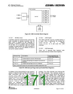
13.16.5.2 SETUP Transactions (IDLE State)
The control transfer consists of 2 – 3 stages of
transactions (Setup – Data - Status or Setup -
Status). The first transaction is a Setup
transaction. A successful Setup transaction
comprises three sequential packets (a token
packet, a data packet, and a handshake
packet), where the data field (payload) of the
data packet is exactly 8 bytes long and are
referred to as the Setup Packet. In the Setup
stage of a control transfer, EP0 will be in the
IDLE state. The USB controller will reject the
data packet if the Setup Packet is not 8 bytes.
Also, the USB controller will examine the
contents of the Setup Packet to determine
whether or not there is a Data stage in the
control transfer. If there is a Data stage, EP0
will switch state to TX (IN transaction) or RX
Firmware should load the EP0 FIFO with the
first
data
packet
and
set
the
USBCS0.INPKT_RDY bit as soon as possible
after the USBCS0.CLR_OUTPKT_RDY bit has
been set. The USBCS0.INPKT_RDY will be
cleared and an EP0 interrupt will be generated
when the data packet has been sent. Firmware
might then load more data packets as
necessary. An EP0 interrupt will be generated
for each packet sent. Firmware must set
USBCS0.DATA_END
in
addition
to
USBCS0.INPKT_RDY when the last data
packet has been loaded. This will start the
Status stage of the control transfer.
EP0 will switch to the IDLE state when the
Status stage has completed. The Status stage
may fail if the USBCS0.SEND_STALL bit is set
to 1. The USBCS0.SENT_STALL bit will then
be asserted and an EP0 interrupt will be
generated as explained in Section 13.16.5.1.
(OUT
transaction)
when
the
USBCS0.CLR_OUTPKT_RDY bit is set to 1 (if
USBCS0.DATA_END=0).
When
a
packet
is
received,
the
USBCS0.OUTPKT_RDYbit will be asserted and
an interrupt request is generated (EP0
interrupt) if the interrupt has been enabled.
Firmware should perform the following when a
Setup Packet has been received:
If USBCS0.INPKT_RDY is not set when
receiving an IN token, the USB Controller will
reply with a NAK to indicate that the endpoint
is working, but temporarily has no data to
send.
1. Unload the Setup Packet from the EP0
FIFO
13.16.5.4 OUT Transactions (RX state)
2. Examine the contents and perform the
appropriate operations
If the control transfer requires data to be
received from the host, the Setup stage will be
followed by one or more OUT transactions in
the Data stage. In this case the USB controller
will be in RX state and only accept OUT
SWRS055D
Page 173 of 243

 TAOS [ TEXAS ADVANCED OPTOELECTRONIC SOLUTIONS ]