Input:
Output:
Current:
Package:
35-55 V
9.6 V
43 A
Quarter-brick
Technical Specification
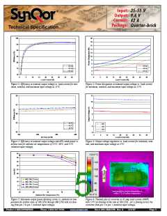
the output variation of the BusQor must be in accordance with the
input voltage range of the non-isolated converters being
employed.
BASIC OPERATION AND FEATURES
With voltages dropping and currents rising, the economics of an
Intermediate Bus Architecture (IBA) are becoming more attractive,
especially in systems requiring multiple low voltages. IBA systems
separate the role of isolation and voltage scaling from regulation
and sensing. The BusQor series bus converter provides isolation
and an unregulated voltage step down in one compact module,
leaving regulation to simpler, less expensive non-isolated con-
verters.
The BusQor architecture is very scalable, meaning multiple bus
converters can be connected directly in parallel to allow current
sharing for higher power applications.
CONTROL FEATURES
REMOTE ON/OFF (Pin 2): The ON/OFF input, Pin 2, permits
the user to control when the converter is on or off. This input is
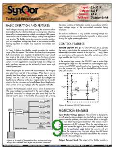
In Figure A below, the BusQor module provides the isolation
stage of the IBA system. The isolated bus then distributes power
to the non-isolated buck regulators to generate the required volt-
age levels at the points of load. In this case, the bucks are rep-
resented with SynQor’s NiQor series of non-isolated DC/DC con-
verters. In many applications requiring multiple low voltage out-
puts, significant savings can be achieved in board space and
overall system costs.
referenced to the return terminal of the input bus,
Vin(-). There
are two versions of the converter that differ by the sense of the
logic used for the ON/OFF input.
In the positive logic version, the ON/OFF input is active high
(meaning that a high turns the converter on). In the negative logic
version, the ON/OFF signal is active low (meaning that a low
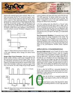
turns the converter on). Figure B is a detailed look of the internal
ON/OFF circuitry.
When designing an IBA system with bus converters, the designer
can select from a variety of bus voltages. While there is no uni-
versally ideal bus voltage, most designs employ one of the fol-
lowing: 12V, 9V, 7.5V, 5V, or 3.3V. Higher bus voltages can
lead to lower efficiency for the buck regulators but are more effi-
cient for the bus converter and provide lower board level distrib-
ution current. Lower bus voltages offer the opposite trade offs.
Vin+
5V
100k
On/Off
49.9k
SynQor’s 9.6Vout BusQor module acts as a true dc transformer.
The output voltage is proportional to the input voltage, with a
specified “turns ratio” or voltage ratio, plus minor drop from the
internal resistive losses in the module. When used in IBA systems,
TTL
100k
Vin-
3.3 V
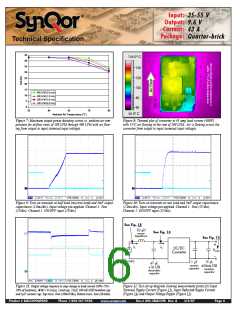
Figure B: Internal ON/OFF pin circuitry
PROTECTION FEATURES
Input Under-Voltage Lockout: The converter is designed to
turn off when the input voltage is too low, helping avoid an input
system instability problem, described in more detail in the appli-
cation note titled “Input System Instability”. The lockout circuitry
is a comparator with DC hysteresis. When the input voltage is ris-
ing, it must exceed the typical Turn-On Voltage Threshold value
(listed on the specification page) before the converter will turn
on. Once the converter is on, the input voltage must fall below
the typical Turn-Off Voltage Threshold value before the converter
will turn off. Also see Figure E.
2.5 V
48Vdc
35-55V
9.6Vdc
BusQor
Converter
1.8 V
1.5 V
0.9 V
NiQor
Converters
Loads
Typical User Board
48Vdc
Front
End
Output Current Limit: The output of the BusQor module is
Figure A: Example of Intermediate Bus Architecture using
BusQor bus converter and NiQor non-isolated converters
Product # BQ55090QPA40
Phone 1-888-567-9596
www.synqor.com
Doc.# 005-2BQ559K Rev. A
3/6/07
Page 9

 SYNQOR [ SYNQOR WORLDWIDE HEADQUARTERS ]