Input:
Output:
Current:
Package:
35-55 V
9.6 V
43 A
Quarter-brick
Technical Specification
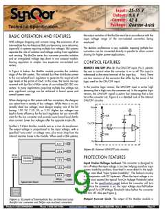
electronically protected against output overloads. When an over-
load current greater than the “DC Current-Limit Inception” speci-
fication is drawn from the output, the output shuts down to zero
volt in a period of 20ms typical (see Figure C). The shutdown
period lasts for a typical period of 250ms (Figure D) after which
the BusQor tries to power up again. If the overload persists, the
output voltage will go through repeated cycles of shutdown and
restart with a duty cycle of 9% (On) and 91% (Off) respectively.
The BusQor module returns (auto resetting) to normal operation
once the overload is removed. The BusQor is designed to survive
cycles of shutdown and restart with a duty cycle of 9% (On) and
91% (Off) respectively. The BusQor module returns (auto reset-
ting) to normal operation once the short circuit is removed. The
BusQor is designed to survive in this mode indefinitely without
damage and without human intervention.
In the Auto resetting mode, also referred to as “Hiccup” mode,
the power drawn from the 48V input is about 5 Watts, most of
which is dissipated into the external fault. It is important that cop-
per traces and pads from the output circuit be designed to with-
stand the short term peaks, although the average current into the
fault may be as low as 2A typical. See Figure 17 for appropriate
waveform.
Output
Current
53A
43A
Over-Temperature Shutdown: A temperature sensor on the
converter senses the average temperature of the module. The
thermal shutdown circuit is designed to turn the converter off
when the temperature at the sensed location reaches the Over-
Temperature Shutdown value. It will allow the converter to turn on
again when the temperature of the sensed location falls by the
amount of the Over-Temperature Shutdown Restart Hysteresis
value.
Output
Voltage
9.6V
0V
20ms
Time
APPLICATION CONSIDERATIONS
Figure C: Output Overload protection diagram (not to scale)
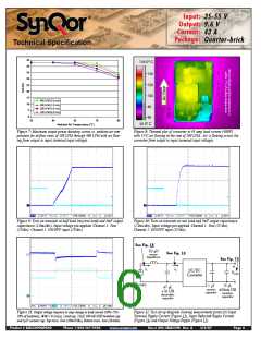
Start-Up Inhibit Period: Figure E details the Start-Up Inhibit
Period for the BusQor module. At time t0, when Vin is applied
with On/Off pin asserted (enabled), the BusQor output begins to
build up. Before time t1, when the input voltage is below the UVL
threshold, the unit is disabled by the Input Under-Voltage Lockout
feature. When the input voltage rises above the UVL threshold,
the Input Under-Voltage Lockout is released, and a typical Startup
Inhibit Period of 3ms is initiated. The output builds up to 90% or
higher of the nominal voltage and stabilizes at the nominal value
of 9.6V in a period of 6ms typical. The rise time from 0V to 90%
is 2ms typical.
in this mode indefinitely without damage and without human
intervention.
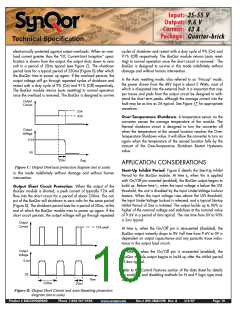
Output Short Circuit Protection: When the output of the
BusQor module is shorted, a peak current of typically 72A will
flow into the short circuit for a period of about 230ms. The out-
put of the BusQor will shutdown to zero volts for the same period
(Figure D). The shutdown period lasts for a period of 20ms, at the
end of which the BusQor module tries to power up again. If the
short circuit persists, the output voltage will go through repeated
Output
Current
72A peak
At time t2, when the On/Off pin is de-asserted (disabled), the
BusQor output instantly drops to 0V. Fall time from 9.6V to 0V is
dependent on output capacitance and any parasitic trace induc-
tance in the output load circuit.
Output
Voltage
At time t3, when the On/Off pin is re-asserted (enabled), the
BusQor module output begins to build up after the inhibit period
of 4ms typical.
9.6V
Refer to the Control Features section of the data sheet for details
on enabling and disabling methods for N and P logic type mod-
ules.
0V
Time
230ms
20ms
Figure D: Output Short Circuit and Auto-Resetting protection
diagram (not to scale)
Product # BQ55090QPA40
Phone 1-888-567-9596
www.synqor.com
Doc.# 005-2BQ559K Rev. A
3/6/07
Page 10

 SYNQOR [ SYNQOR WORLDWIDE HEADQUARTERS ]