Input:
Output:
Current:
Package:
35-55 V
9.6 V
43 A
Quarter-brick
Technical Specification
For applications that require mounting parts BELOW the BusQor
module, one should be aware of potential high levels of electro-
magnetic interference, in addition to safety keep out. Users are
advised to consult SynQor Applications engineering in such
applications.
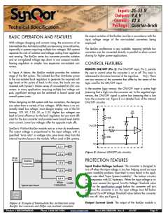
Vin
UVLO
Copper Keep Out Area: Keep out areas shown in Figure F are to
be observed for Top layer copper traces and vias. Internal layers
buried one or more layers may be exempt, depending on the
PCB material grade and thickness. Users are advised to consult
UL standards for details.
On/Off
(N logic)
OFF
ON
t0
t1
t2
t3
t
All layers including top and bottom, are subject to the keep out
areas shown around Primary pins of BusQor module. Actual keep
outs along the surface (Creepage) may vary depending on the
PCB material CTI. Users are advised to consult UL standards for
details.
Vout
12V
Time
4ms
6ms
Bridging Components: Bridging components like EMI filter capac-
itors required to be placed as close as possible to the BusQor
module for optimum performance must observe the
clearance/creepage requirements of 0.04"(40 mils) between
pads to maintain compliance to UL standards for the overall
power system.
3ms
Figure E: Power Up/Down Diagram (not to scale) showing
Start-Up Inhibit Period.
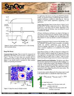
Keep Out Areas:
Note: Referenced keep out widths are adequate to withstand UL's
Basic Insulation Dielectric strength tests for approved PCB mate-
rials. Applications requiring Double or Reinforced insulation must
double the keep out widths shown in Figure F. Keep out areas
shown have standard margins above UL's minimum requirements.
Component Keep Out Area: Keep out areas for components not
referenced to the Primary circuit are shown in shaded areas in
Figure F. The keep out areas shown are consistent with UL's
requirements for Basic Insulation of 0.04" (40 mils) for Pollution
degree 2. User should consult UL standards for other insulation
classes and operating environments.
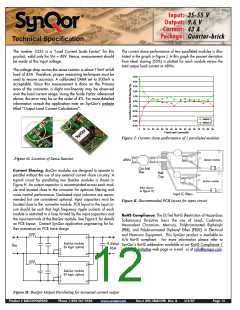
Output Load Current Calculation: The BusQor series allows
the converter output load to be measured without adding a cur-
rent loop or external shunt resistor to the designer’s PCB board
under test. On the top side of the BusQor converter is a current
sense resistor as shown in Figure G. The output load current is
proportional to the voltage drop across this sense resistor. This
calculation is detailed below.
0.01”
A current sense resistor referenced to the primary input is used
in the equation below to calculate the output load current.
0.023”
Iload = (VRsense(load) - VRsense(no load) ) x 3333
where:
Bridging
Capacitor
0.01”
Iload = output load current
1.50”
V
= voltage across the sense resistor with
Rsense(load)
Primary
Secondary
converter under load
V
= voltage across the sense resistor with
converter at zero load
Rsense(no load)
Figure F: Keep Out Areas for BusQor module
Product # BQ55090QPA40
Phone 1-888-567-9596
www.synqor.com
Doc.# 005-2BQ559K Rev. A
3/6/07
Page 11

 SYNQOR [ SYNQOR WORLDWIDE HEADQUARTERS ]