Input:
Output:
Current:
Package:
35-55 V
9.6 V
43 A
Quarter-brick
Technical Specification
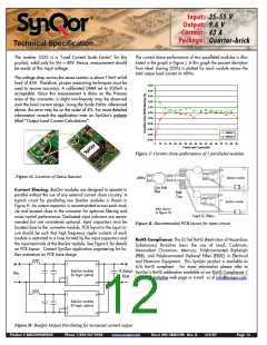
The number 3333 is a “Load Current Scale Factor” for this
product, valid only for Vin = 48V. Hence, measurement should
be made at this input voltage.
The current share performance of two paralleled modules is illus-
trated in the graph in Figure J. In this graph the percent deviation
from ideal sharing (50%) is plotted for each module versus the
total output load current at 48Vin.
The voltage drop across the sense resistor is about 13mV at full
load of 43A. Therefore, proper measuring techniques must be
used to ensure accuracy. A calibrated DMM set to 300mV is
acceptable. Since this measurement is done on the Primary
area of the converter, a slight non-linearity may be observed
over the load current range. Using the Scale Factor referenced
above, the error may be on the order of 4%. For more detailed
information consult the application note on SynQor’s website
titled “Output Load Current Calculations”.
5.0%
4.0%
3.0%
2.0%
1.0%
0.0%
-1.0%
-2.0%
-3.0%
Module 1
-4.0%
Module 2
-5.0%
5
10 15 20 25 30 35 40 45 50 55 60 65 70 75 80 85
Total Load Current (A)
Figure J: Current share performance of 2 paralleled modules
Figure G: Location of Sense Resistor
BusQor module
48Vin
CM EMI
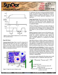
Current Sharing: BusQor modules are designed to operate in
parallel without the use of any external current share circuitry. A
typical circuit for paralleling two BusQor modules is shown in
Figure H. An output capacitor is recommended across each mod-
ule and located close to the converter for optimum filtering and
noise control performance. Dedicated input inductors are recom-
mended but are considered optional. Input capacitors must be
located close to the converter module. PCB layout in the input cir-
cuit should be such that high frequency ripple currents of each
module is restricted to a loop formed by the input capacitors and
the input terminals of the BusQor module. See Figure K for details
on PCB layout. Contact SynQor application engineering for fur-
ther assistance on PCB trace design.
filter
Bulk
Cap
BusQor module
(Not shown
in Figure H)
Input LC filters
Figure K: Recommended PCB layout for input circuit
RoHS Compliance: The EU led RoHS (Restriction of Hazardous
Substances) Directive bans the use of Lead, Cadmium,
Hexavalent Chromium, Mercury, Polybrominated Biphenyls
(PBB), and Polybrominated Diphenyl Ether (PBDE) in Electrical
and Electronic Equipment. This SynQor product is available as
6/6 RoHS compliant. For more information please refer to
SynQor’s RoHS addendum available at our RoHS Compliance /
Lead Free Initiative web page or e-mail us at rohs@synqor.com.
1
5
BusQor module
(N logic option)
9.6Vout
86A
Vin
2
3
4
5
1
BusQor module
(N logic option)
2
3
4
Figure H: BusQor Output Paralleling for increased current output.
Product # BQ55090QPA40
Phone 1-888-567-9596
www.synqor.com
Doc.# 005-2BQ559K Rev. A
3/6/07
Page 12

 SYNQOR [ SYNQOR WORLDWIDE HEADQUARTERS ]