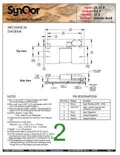
Input:
Output:
Current:
Package:
35-55 V
9.6 V
43 A
Quarter-brick
Technical Specification
45
40
35
30
25
20
15
400 LFM (2.0 m/s)
10
5
300 LFM (1.5 m/s)
200 LFM (1.0 m/s)
100 LFM (0.5 m/s)
0
25
40
55
Ambient Air Temperature (ºC)
70
85
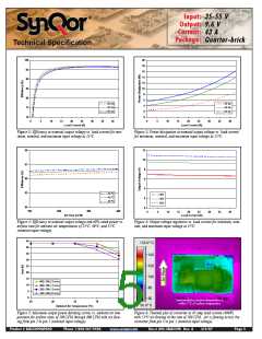
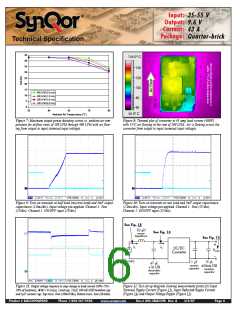
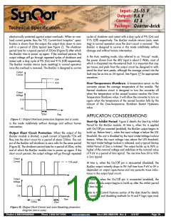
Figure 7: Maximum output power derating curves vs. ambient air tem-
perature for airflow rates of 100 LFM through 400 LFM with air flow-
ing from output to input (nominal input voltage).
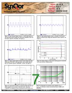
Figure 8: Thermal plot of converter at 43 amp load current (400W)
with 55 C air flowing at the rate of 200 LFM. Air is flowing across the
converter from output to input (nominal input voltage).
°
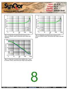
Figure 9: Turn-on transient at half load (resistive load) and 3mF output
capacitance (2.0ms/div). Input voltage pre-applied. Channel 1: Vout
(2V/div). Channel 2: ON/OFF input (2V/div).
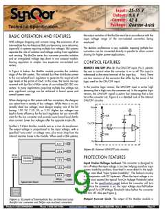
Figure 10: Turn-on transient at zero load and 3mF output capacitance
(2.0ms/div). Input voltage pre-applied. Channel 1: Vout (2V/div).
Channel 2: ON/OFF input (2V/div).
See Fig. 14
10 µH
See Fig. 13
source
impedance
See Fig. 15
iS
iC
DC/DC
Converter
VOUT
VSOURCE
15
µ
Ω
F,
ESR
1 µF
47 µF,
ceramic
450m
<1
Ω ESR
capacitor
tantalum
electrolytic
capacitor
capacitor
Figure 11: Output voltage response to step-change in load current (50%-75%-
Figure 12: Test set-up diagram showing measurement points for Input
Terminal Ripple Current (Figure 13), Input Reflected Ripple Current
(Figure 14) and Output Voltage Ripple (Figure 15).
50% of Iout(max); dI/dt = 0.1A/µs). Load cap: 15µF, 100 mΩ ESR tantalum cap
and 1 F ceramic cap. Top trace: Vout (200mV/div), Bottom trace: Iout (10A/div).
µ
Product # BQ55090QPA40
Phone 1-888-567-9596
www.synqor.com
Doc.# 005-2BQ559K Rev. A
3/6/07
Page 6

 SYNQOR [ SYNQOR WORLDWIDE HEADQUARTERS ]