Input:
Output:
Current:
Package:
35-55 V
9.6 V
43 A
Quarter-brick
Technical Specification
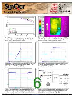
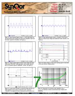
Figure 13: Input Terminal Ripple Current, i , at full rated output cur-
Figure 14: Input reflected ripple current, i , through a 10 µH source
s
c
rent and nominal input voltage with 10
µH source impedance and 47
µF
inductor at nominal input voltage and rated load current (5mA/div). See
Figure 12.
electrolytic capacitor (50 mA/div). See Figure 12.
12
10
8
6
4
35 Vin
48 Vin
2
55 Vin
0
0
10
20
30
40
50
60
Load Current (A)
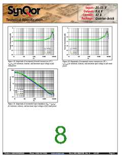
Figure 15: Output voltage ripple at nominal input voltage and rated
load current (50 mV/div). Load capacitance: 1 F ceramic capacitor
and 15 F tantalum capacitor. Bandwidth: 20 MHz. See Figure 12.
Figure 16: Output voltage vs. load current showing typical current limit
curves and converter shutdown points.
µ
µ
1
0.1
0.01
35 Vin
48 Vin
55 Vin
0.001
10
100
1,000
Hz
10,000
100,000
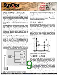
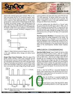
Figure 18: Magnitude of incremental output impedance (Z
=
Figure 17: Load current (10A/div) as a function of time when the con-
verter attempts to turn on into a 1 m short circuit. Top trace
(5.0ms/div) is an expansion of the on-time portion of the bottom trace.
out
v
/i ) for minimum, nominal, and maximum input voltage at full
Ω
out out
rated power.
Product # BQ55090QPA40
Phone 1-888-567-9596
www.synqor.com
Doc.# 005-2BQ559K Rev. A
3/6/07
Page 7

 SYNQOR [ SYNQOR WORLDWIDE HEADQUARTERS ]