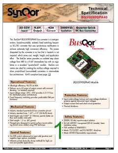
Input:
Output:
Current:
Package:
35-55 V
9.6 V
43 A
Quarter-brick
Technical Specification
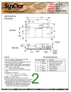
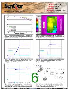
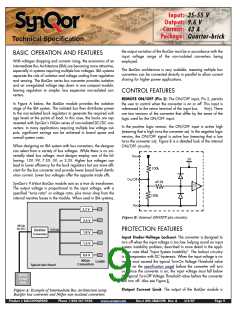
MECHANICAL
DIAGRAM
2.30
(58.4)
2.00
(50.8)
0.14
(3.6)
1
5
4
Top View
1.45
(36.8)
2
3
0.600
(15.24)
0.300
(7.62)
0.600
(15.24)
0.43
(10.9)
0.467 +0.020
(11.86 +0.5)
0.145
(3.68)
See Note 3
Side View
0.063 +0.020
Lowest
Component
(1.6 +0.5)
Flanged Pin
See Note 10
Bottom side
Clearance
See Note 9
Load Board
NOTES
PIN DESIGNATIONS
1) Pins 1-3 are 0.040” (1.02mm) diameter with 0.080”
(2.03 mm) diameter standoff shoulders.
Pin No. Name
Function
1
2
Vin(+)
ON/OFF
Input Positive (35V - 55V)
Logic control input to turn
converter on and off.
Input Negative
Output Negative
Output Positive
2) Pins 4 and 5 are 0.062” (1.57 mm) diameter with 0.100”
(2.54 mm) diameter standoff shoulders.
3) Other pin extension lengths available. Recommended pin
length is 0.03” (0.76mm) greater than the PCB thickness.
4) All Pins: Material - Copper Alloy
Finish - Matte Tin over Nickel plate
3
4
5
Vin(-)
Vout(-)
Vout(+)
5) Undimensioned components are shown for visual reference
only.
6) All dimensions in inches (mm)
Tolerances: x.xx +/-0.02 in. (x.x +/-0.5mm)
x.xxx +/-0.010 in. (x.xx +/-0.25mm)
7) Weight: 1.5 oz. (42 g) typical
8) Workmanship: Meets or exceeds IPC-A-610C Class II
9) UL/TUV standards require a clearance of 0.04” (1.02mm)
around primary areas of the module. Refer to section on
Keep Out Areas under Application Considerations for details.
10) The flanged pins are designed to permit surface mount
soldering (allowing to avoid the wave soldering process)
through the use of the flanged pin-in-paste technique.
Product # BQ55090QPA40
Phone 1-888-567-9596
www.synqor.com
Doc.# 005-2BQ559K Rev. A
3/6/07
Page 2

 SYNQOR [ SYNQOR WORLDWIDE HEADQUARTERS ]