SMD1102 / 1103 / 1113
limit data is forthcoming), and the data bits are from the stored with the upper and lower limits in the NV registers.
upper limit. The fifth and final byte represents the Figure 8 details these conditions. If an out-of-limit
remaining eight bits of the upper limit data.
conditionisdetectedtheSMD1102/1103/1113willtempo-
rarily remove itself from the auto-increment mode (if that
was selected), and monitor the channel that caused the
alert. There must be five successive conversions result-
ing in an out-of-limit condition before the SMD1102/1103/
1113 will signal an alert. If at any time during the verify
routinetheout-of-limitconditionisnegatedtheSMD1102/
1103/1113 will re-enter its Auto-Monitor routine. If a valid
alert condition has been detected the device will halt the
Auto-Monitor function and await instructions from the
host.
Auto-Monitor
Auto-Monitoroperationtakesfulladvantageoftheunique
capabilitiesoftheSMD1102/1103/1113. Eachdevicecan
autonomously monitor the analog channels, compare the
conversion data against stored, nonvolatile limit regis-
ters, and, if necessary, alert the host to out-of-limit
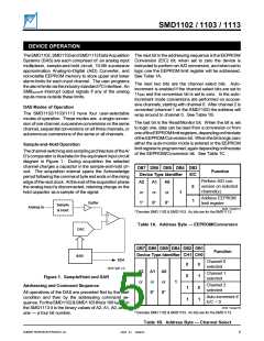
conditions. The command string to enter the Auto-
Monitor mode is shown in Figure 7. It consists of a start
condition followed by the device type identifier (slave
address), the EEPROM/Conversion bit set to zero, the
channel select bits, and the Read/Monitor bit set to zero.
After Acknowledge the host issues a Stop condition in
order to initiate the Auto-Monitor process. Setting the
channel select bits to a particular channel limits the
monitoringtothatchannel. Settingthechannelselectbits
to “11” allows all three inputs to be monitored in succes-
sion (auto-increment). In the case of the 1102 the limit
registers for channel 2 should be set so that the alert
cannot be generated from this channel (see the following
section "Alert Conditions"). The Auto-Monitor operation
mustbeterminatedbeforefurthercommunicationwiththe
device. The Auto-Monitor function is automatically shut
down when an alert is asserted. Any Read operation will
also halt Auto-Monitor, and, if an alert has occurred, it will
clear the alert along with the stored information of the
channel that prompted the alert.
IfanyoneofthechannelsisnotbeingusedwhiletheAuto-
Monitor function is enabled that channel must have its
alert conditions as well as its limit registers set so that it
does not cause an alert. This is accomplished by first
setting the alert region inside the limits (i.e., set monitor
option bits to either 10BIN or 11BIN), and then setting the
lower limit above the upper limit.
Alert Response
The SMD1102, SMD1103 and SMD1113 are considered
slavedevices. TheydonotgenerateclocksontheSCLpin
or take control of bus activity. However, the SMBus
specification, an extension of the I2C specification, does
allowslavedevicestheabilitytogenerateinterruptstoget
the attention of the host by pulling SMBALERT# low.
After the SMD1102/1103/1113 has issued an alert by
pulling SMBALERT# low the alert can only be reset by
addressing the device. If there is more than one device
ontheSMBuscapableofgeneratinganalert,thehostmay
determine the offending device by issuing an Alert Re-
sponse Address (ARA). The ARA is a general call to all
devices, but only an SMBus compatible device will recog-
nizethecall, andonlyadevicethatgeneratedaninterrupt
will respond to the call. The DAS responds by acknowl-
edging the ARA, and then by sending its device address
on the SDA line, as shown in Figure 9. Embedded in the
device address is the channel that caused the alert. If
more than one SMBus compliant device has responded
to the ARA, standard I2C bus arbitration allows the device
with the lowest address to be serviced first.
Note: a Read operation that is used to halt the
Auto-Monitor function will not return valid data.
Alert Conditions
For each channel the host can select one of four condi-
tions that will generate an alert while Auto-Monitor is
active. Theseconditionsaredeterminedbytheoptionbits
SCL
Note: ThedeviceaddressofanSMD1113should
not be set with A2, A1 and A0 all equal to zero.
This would create an address conflict with the
SMBALERT# broadcast message.
1
0
0
1
0
CH1 CH0
0
SDA
S
T
O
P
S
T
A
R
T
A
C
K
Channel
Address
Device Type
Identifier
2033 Fig07
Figure 7. Begin Auto-Monitor Command
SUMMIT MICROELECTRONICS, Inc.
2033 8.1 10/04/01
8

 SUMMIT [ SUMMIT MICROELECTRONICS, INC. ]