SMD1102 / 1103 / 1113
INTRODUCTION
The SMD1102, SMD1103 and SMD1113 each contain a automaticallymonitoroneormoreanaloginputchannels.
10-Bit data acquisition system (DAS) with dedicated EE- If any input signal moves beyond its user-programmed
PROM alarm limit storage. The three devices communi- limitsthehostisnotifiedbytheSMBALERT#output,enabling
cate with the host µP via a standard two-wire I2C serial fault prediction in telecom line card applications, as an
interface. AfterinitializationtheSMD1102/1103/1113can example.
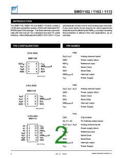
PIN CONFIGURATION
PIN NAMES
1102
8-Pin SOIC
SMD1102
AIN0, AIN1
Analog channel inputs
Power supply return
Reference input
Serial Clock
GND
REFIN
SCL
1
2
3
4
8
7
6
5
V
DD
REF
IN
SMB
SCL
SDA
#
A 1
ALERT
IN
A 0
IN
SDA
Serial Data
GND
SMBALERT
VDD
#
Interrupt output
Power Supply
2033 8 PCon-2
1103
8-Pin SOIC
SMD1103
AIN0, AIN1, AIN2
GND
Analog channel inputs
Power supply return
Serial Clock
SCL
1
2
3
4
8
7
6
5
VDD
SMBALERT
SCL
SDA
AIN
2
AIN1
AIN0
GND
#
SDA
Serial Data
SMBALERT
VDD
#
Interrupt output
Power Supply
2033 8 PCon-3
1113
14-Pin SOIC
SMD1113
CE#
Chip Enable
A2, A1, A0
I2C Address select inputs
Analog channel inputs
Power supply return
Reference input
Serial Clock
AIN0, AIN1, AIN2
GND
1
2
3
4
5
6
7
14
13
12
11
10
9
VDD
CE#
REFIN
NC
SMBALERT
SCL
A0
A1
A2
AIN2
AIN1
AIN0
GND
REFIN
#
SCL
SDA
Serial Data
8
SDA
SMBALERT
VDD
#
Interrupt output
Power Supply
2033 14 PCon
SUMMIT MICROELECTRONICS, Inc.
2033 8.1 10/04/01
2

 SUMMIT [ SUMMIT MICROELECTRONICS, INC. ]