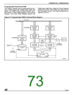
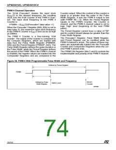
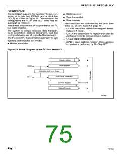
UPSD3212C, UPSD3212CV
Serial Status Register (S2STA)
S2STA is a “Read-only” register. The contents of
this register may be used as a vector to a service
routine. This optimized the response time of the
3. A data byte has been received or transmitted in
Master Mode (even if arbitration is lost): ack_int
4. A data byte has been received or transmitted as
selected slave: ack_int
5. A stop condition is received as selected slave
receiver or transmitter: stop_int
Data Shift Register (S2DAT)
S2DAT contains the serial data to be transmitted
or data which has just been received. The MSB
(Bit 7) is transmitted or received first; that is, data
shifted from right to left.
2
software and consequently that of the I C bus. The
2
status codes for all possible modes of the I C bus
interface are given Table 54.
This flag is set, and an interrupt is generated, after
any of the following events occur:
1. Own slave address has been received during
AA = 1: ack_int
2. The general call address has been received
while GC(S2ADR.0) = 1 and AA = 1:
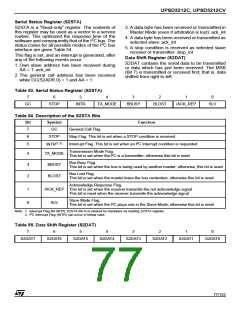
Table 53. Serial Status Register (S2STA)
7
6
5
4
3
2
1
0
GC
STOP
INTR
TX_MODE
BBUSY
BLOST
/ACK_REP
SLV
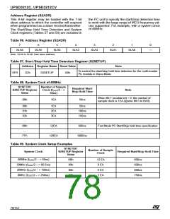
Table 54. Description of the S2STA Bits
Bit
7
Symbol
GC
Function
General Call Flag
Stop Flag. This bit is set when a STOP condition is received
6
STOP
(1,2)
5
Interrupt Flag. This bit is set when an I²C Interrupt condition is requested
INTR
Transmission Mode Flag.
This bit is set when the I²C is a transmitter; otherwise this bit is reset
4
3
2
TX_MODE
BBUSY
Bus Busy Flag.
This bit is set when the bus is being used by another master; otherwise, this bit is reset
Bus Lost Flag.
BLOST
This bit is set when the master loses the bus contention; otherwise this bit is reset
Acknowledge Response Flag.
1
0
/ACK_REP This bit is set when the receiver transmits the not acknowledge signal
This bit is reset when the receiver transmits the acknowledge signal
Slave Mode Flag.
SLV
This bit is set when the I²C plays role in the Slave Mode; otherwise this bit is reset
Note: 1. Interrupt Flag Bit (INTR, S2STA Bit 5) is cleared by Hardware as reading S2STA register.
2
2. I C Interrupt Flag (INTR) can occur in below case.
Table 55. Data Shift Register (S2DAT)
7
6
5
4
3
2
1
0
S2DAT7
S2DAT6
S2DAT5
S2DAT4
S2DAT3
S2DAT2
S2DAT1
S2DAT0
77/152

 STMICROELECTRONICS [ ST ]