UPSD3212C, UPSD3212CV
PWM 4 Channel Operation
The 16-bit Prescaler1 divides the input clock
Counter output. When the content of the counter is
equal to or greater than the value in the Pulse
Width Register, it sets the PWM 4 output to low
(with PWMP Bit = 0). When the Period Register
equals to the PWM4 Counter, the Counter is
cleared, and the PWM 4 channel output is set to
logic 'high' level (beginning of the next PWM
pulse).
The Period Register cannot have a value of “00”
and its content should always be greater than the
Pulse Width Register.
The Prescaler1 Register, Pulse Width Register,
and Period Register can be modified while the
PWM 4 channel is active. The values of these reg-
isters are automatically loaded into the Prescaler
Counter and Comparator Registers when the cur-
rent PWM 4 period ends.
(f
OSC
/2) to the desired frequency, the resulting
clock runs the 8-bit Counter of the PWM 4 chan-
nel. The input clock frequency to the PWM 4
Counter is:
f PWM4 = (f
/2)/(Prescaler1 data value +1)
OSC
When the Prescaler1 Register (B4h, B3h) is set to
data value '0,' the maximum input clock frequency
to the PWM 4 Counter is f
as 20MHz.
/2 and can be as high
OSC
The PWM 4 Counter is a free-running, 8-bit
counter. The output of the counter is compared to
the Compare Registers, which are loaded with
data from the Pulse Width Register (PWM4W,
ABh) and the Period Register (PWM4P, AAh). The
Pulse Width Register defines the pulse duration or
the Pulse Width, while the Period Register defines
the period of the PWM. When the PWM 4 channel
is enabled, the register values are loaded into the
Comparator Registers and are compared to the
The PWMCON Register (Bits 5 and 6) controls the
enable/disable and polarity of the PWM 4 channel.
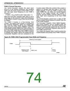
Figure 38. PWM 4 With Programmable Pulse Width and Frequency
Defined by Period Register
PWM4
Defined by Pulse
Switch Level
RESET
Counter
Width Register
AI07090
74/152

 STMICROELECTRONICS [ ST ]