UPSD3212C, UPSD3212CV
Table 41. Timer/Counter 2 Operating Modes
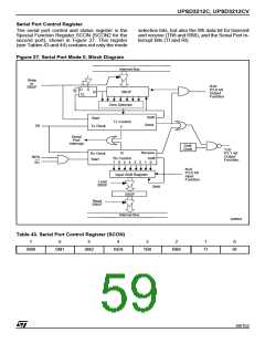
T2CON
Input Clock
T2MOD T2CON P1.1
RxCLK
or
TxCLK
Mode
Remarks
CP/
RL2
External
(P1.0/T2)
DECN
EXEN T2EX
TR2
Internal
0
0
0
0
1
1
0
0
0
1
x
reload upon overflow
reload trigger (falling
edge)
16-bit
Auto-
reload
↓
MAX
f
/12
OSC
f
/24
OSC
0
0
0
0
1
1
1
1
x
x
0
1
Down counting
Up counting
16-bit Timer/Counter
(only up counting)
0
0
1
1
1
x
1
1
1
x
x
x
0
1
0
x
↓
x
MAX
16-bit
Capture
f
f
/12
/12
OSC
OSC
f
f
/24
OSC
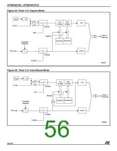
Capture (TH1,TL2) →
(RCAP2H,RCAP2L)
No Overflow Interrupt
Request (TF2)
MAX
Baud Rate
Generator
/24
OSC
Extra External Interrupt
(Timer 2)
1
x
x
x
1
0
x
x
1
x
↓
Off
x
Timer 2 stops
—
—
Note: ↓ = falling edge
Table 42. Description of the T2CON Bits
Bit
Symbol
Function
Timer 2 Overflow Flag. Set by a Timer 2 overflow, and must be cleared by software. TF2
will not be set when either (RCLK, RCLK1)=1 or (TCLK, TCLK)=1
7
TF2
Timer 2 External Flag set when either a capture or reload is caused by a negative
transition on T2EX and EXEN2=1. When Timer 2 Interrupt is enabled, EXF2=1 will
cause the CPU to vector to the Timer 2 Interrupt routine. EXF2 must be cleared by
software
6
EXF2
Receive Clock Flag (UART 1). When set, causes the serial port to use Timer 2 overflow
pulses for its receive clock in Modes 1 and 3. TCLK=0 causes Timer 1 overflow to be
used for the receive clock
(1)
5
4
3
RCLK
Transmit Clock Flag (UART 1). When set, causes the serial port to use Timer 2 overflow
pulses for its transmit clock in Modes 1 and 3. TCLK=0 causes Timer 1 overflow to be
used for the transmit clock
(1)
TCLK
Timer 2 External Enable Flag. When set, allows a capture or reload to occur as a result
of a negative transition on T2EX if Timer 2 is not being used to clock the serial port.
EXEN2=0 causes Time 2 to ignore events at T2EX
EXEN2
2
1
TR2
Start/stop control for Timer 2. A logic 1 starts the timer
Timer or Counter Select for Timer 2. Cleared for timer operation (input from internal
C/T2
system clock, t
); set for external event counter operation (negative edge triggered)
CPU
Capture/Reload Flag. When set, capture will occur on negative transition of T2EX if
EXEN2=1. When cleared, auto-reload will occur either with TImer 2 overflows, or
negative transitions of T2EX when EXEN2=1. When either (RCLK, RCLK1)=1 or (TCLK,
TCLK)=1, this bit is ignored, and timer is forced to auto-reload on Timer 2 overflow
0
CP/RL2
Note: 1. The RCLK1 and TCLK1 Bits in the PCON Register control UART 2, and have the same function as RCLK and TCLK.
55/152

 STMICROELECTRONICS [ ST ]