UPSD3212C, UPSD3212CV
USART Interrupt
– The USART Interrupt is generated by RI (Re-
ceive Interrupt) OR TI (Transmit Interrupt).
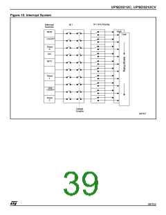
A low priority interrupt may be interrupted by a
high priority interrupt level interrupt. A high priority
interrupt routine cannot be interrupted by any oth-
er interrupt source. If two interrupts of different pri-
ority occur simultaneously, the high priority level
request is serviced. If requests of the same priority
are received simultaneously, an internal polling
sequence determines which request is serviced.
Thus, within each priority level, there is a second
priority structure determined by the polling se-
quence.
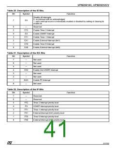
– When the USART Interrupt is generated, the
corresponding request flag must be cleared by
the software. The interrupt service routine will
have to check the various USART registers to
determine the source and clear the correspond-
ing flag.
– Both USART’s are identical, except for the addi-
tional interrupt controls in the Bit 4 of the addi-
tional interrupt control registers (A7H, B7H).
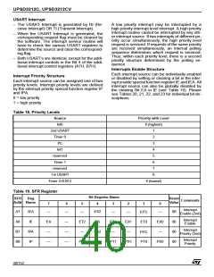
Interrupts Enable Structure
Each interrupt source can be individually enabled
or disabled by setting or clearing a bit in the inter-
rupt enable special function register IE and IEA. All
interrupt source can also be globally disabled by
the clearing Bit EA in IE (see Table 19). Please
see Tables 20, 21, 22, and 23 for individual bit de-
scriptions.
Interrupt Priority Structure
Each interrupt source can be assigned one of two
priority levels. Interrupt priority levels are defined
by the interrupt priority special function register IP
and IPA.
0 = low priority
1 = high priority
Table 18. Priority Levels
Source
Int0
Priority with Level
0 (highest)
2nd USART
Timer 0
1
2
I²C
Int1
3
4
reserved
Timer 1
5
6
reserved
1st USART
Timer 2+EXF2
7
8
9 (lowest)
Table 19. SFR Register
Bit Register Name
SFR
Addr Name
Reg
Reset
Value
Comments
7
6
5
4
3
2
1
0
Interrupt
Enable (2nd)
2
A7
A8
B7
B8
IEA
IE
—
—
—
ES2
—
—
—
00
00
00
00
EI C
Interrupt
Enable
EA
—
—
—
—
ET2
—
ES
PS2
PS
ET1
—
EX1
—
ET0
EX0
—
Interrupt
Priority (2nd)
2
IPA
IP
PI C
Interrupt
Priority
—
PT2
PT1
PX1
PT0
PX0
40/152

 STMICROELECTRONICS [ ST ]