UPSD3212C, UPSD3212CV
POWER-SAVING MODE
Two software selectable modes of reduced power
consumption are implemented (see Table 25).
Idle Mode
The following Functions are Switched Off.
– CPU (Halted)
The following Function Remain Active During Idle
Mode.
Idle Mode
The instruction that sets PCON.0 is the last in-
struction executed in the normal operating mode
before Idle Mode is activated. Once in the Idle
Mode, the CPU status is preserved in its entirety:
Stack pointer, Program counter, Program status
word, Accumulator, RAM and All other registers
maintain their data during Idle Mode.
– External Interrupts
– Timer 0, Timer 1, Timer 2
– PWM Units
There are three ways to terminate the Idle Mode.
– Activation of any enabled interrupt will cause
PCON.0 to be cleared by hardware terminating
Idle mode. The interrupt is serviced, and follow-
ing return from interrupt instruction RETI, the
next instruction to be executed will be the one
which follows the instruction that wrote a logic '1'
to PCON.0.
– USART
– 8-bit ADC
2
– I C Interface
Note: Interrupt or RESET terminates the Idle
Mode.
Power-Down Mode
– System Clock Halted
– LVD Logic Remains Active
– SRAM contents remains unchanged
– The SFRs retain their value until a RESET is as-
serted
Note: The only way to exit Power-down Mode is a
RESET.
Power Control Register
– External hardware reset: the hardware reset is
required to be active for two machine cycle to
complete the RESET operation.
– Internal reset: the microcontroller restarts after
3 machine cycles in all cases.
Power-Down Mode
The instruction that sets PCON.1 is the last exe-
cuted prior to going into the Power-down Mode.
Once in Power-down Mode, the oscillator is
stopped. The contents of the on-chip RAM and the
Special Function Register are preserved.
The Idle and Power-down Modes are activated by
software via the PCON register (see Tables 26
and Table 27, page 44).
The Power-down Mode can be terminated by an
external RESET.
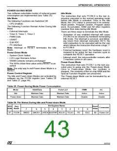
Table 25. Power-Saving Mode Power Consumption
2
Mode
Addr/Data
Ports1,3,4
PWM
I C
Idle
Maintain Data
Maintain Data
Maintain Data
Maintain Data
Active
Active
Disable
Power-down
Disable
Table 26. Pin Status During Idle and Power-down Mode
Bit Register Name
SFR
Reg
Reset
Value
Comments
Addr Name
7
6
5
4
3
2
1
0
87 PCON
SMOD
SMOD1 LVREN ADSFINT RCLK1 TCLK1
PD
IDLE
00
Power Ctrl
43/152

 STMICROELECTRONICS [ ST ]