UPSD3212C, UPSD3212CV
INTERRUPT SYSTEM
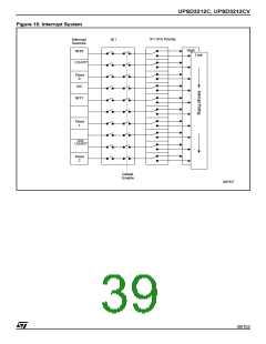
There are interrupt requests from 10 sources as
follows (see Figure 16, page 39).
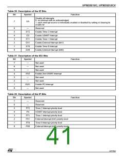
– These flags are cleared by the internal hard-
ware when the interrupt is serviced.
■ INT0 External Interrupt
■ 2nd USART Interrupt
■ Timer 0 Interrupt
Timer 2 Interrupt
– Timer 2 Interrupt is generated by TF2 which is
set by an overflow of Timer 2. This flag has to be
cleared by the software - not by hardware.
2
■ I C Interrupt
– It is also generated by the T2EX signal (Timer 2
External Interrupt P1.1) which is controlled by
EXEN2 and EXF2 Bits in the T2CON register.
■ INT1 External Interrupt (or ADC Interrupt)
■ Timer 1 Interrupt
2
I C Interrupt
■ USART Interrupt
2
– The interrupt of the I C is generated by Bit INTR
in the register S2STA.
– This flag is cleared by hardware.
External Int1
– The INT1 can be either level active or transition
active depending on Bit IT1 in register TCON.
The flag that actually generates this interrupt is
Bit IE1 in TCON.
■ Timer 2 Interrupt
External Int0
– The INT0 can be either level-active or transition-
active depending on Bit IT0 in register TCON.
The flag that actually generates this interrupt is
Bit IE0 in TCON.
– When an external interrupt is generated, the
corresponding request flag is cleared by the
hardware when the service routine is vectored
to only if the interrupt was transition activated.
– If the interrupt was level activated then the inter-
rupt request flag remains set until the requested
interrupt is actually generated. Then it has to de-
activate the request before the interrupt service
routine is completed, or else another interrupt
will be generated.
Timer 0 and 1 Interrupts
– The ADC can take over the External INT1 to
generate an interrupt on conversion being com-
pleted
– Timer 0 and Timer 1 Interrupts are generated by
TF0 and TF1 which are set by an overflow of
their respective Timer/Counter registers (except
for Timer 0 in Mode 3).
38/152

 STMICROELECTRONICS [ ST ]