TS5070 - TS5071
ELECTRICAL OPERATING CHARACTERISTICS (continued)
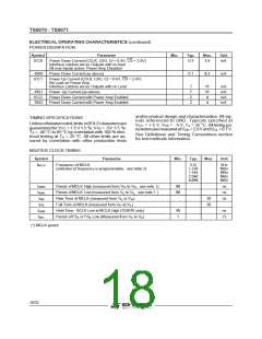
POWER DISSIPATION
Symbol
Parameter
Min.
Typ.
Max.
1.5
Unit
ICC0
Power Down Current (CCLK, CI/O, CI = 0.4V, CS = 2.4V)
Interface Latches set as Outputs with no load
All over Inputs active, Power Amp Disabled
0.3
mA
-ISS0
ICC1
Power Down Current (as above)
0.1
0.3
mA
Power Up Current (CCLK, CI/O, CI = 0.4V, CS = 2.4V)
No Load on Power Amp
Interface Latches set as Outputs with no Load
7
7
2
2
11
11
4
mA
mA
mA
mA
-ISS1
ICC2
-ISS2
Power Up Current (as above)
Power Down Current with Power Amp Enabled
Power Down Current with Power Amp Enabled
4
and/orproduct design and characterization. All sig-
nals referenced to GND. Typicals specified at
TIMING SPECIFICATIONS
Unlessotherwisenoted,limits inBOLDcharactersare
°
VCC = + 5 V, VSS = -5 V, TA = 25 C. All timing pa-
±
±
.
guaranteedfor VCC =+ 5 V 5 %;VSS = -5V 5 %
TA = -40 °C to 85 °C bycorrelationwith 100 % elec-
trical testing at TA = 25 °C. All other limits are as-
sured by correlation with other production tests
rametersaremeasuredatVOH =2.0V andVOL =0.7V.
See Definitions and Timing Conventions section
for test methods information.
MASTER CLOCK TIMING
Symbol
Parameter
Min.
Typ.
Max.
Unit
fMCLK
Frequency of MCLK
(selection of frequency is programmable, see table 2)
512
kHz
MHz
MHz
MHz
MHz
1.536
1.544
2.048
4.096
tWMH
tWML
tRM
Period of MCLK High (measured from VIH to VIH, see note 1)
Period of MCLK Low (measured from VIL to VIL, see note 1 )
Rise Time of MCLK (measured from VIL or VIH)
80
80
ns
ns
ns
30
30
tFM
Fall Time of MCLK (measured from VIH to VIL)
tHBM
tWFL
Hold Time, BCLK Low to MCLK High (TS5070 only)
Period of FSX or FSR Low (Measured from VIL to VIL)
50
ns
(*)
1
(*) MCLK period
18/32

 STMICROELECTRONICS [ ST ]