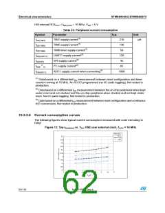
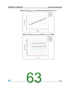
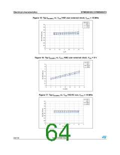
Electrical characteristics
STM8S903K3 STM8S903F3
Min Typ Max Unit
Symbol
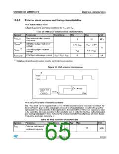
Parameter
Conditions
RF
Feedback resistor
-
220
-
kΩ
C(1)
Recommended load
capacitance(2)
-
-
20
pF
IDD(HSE)
HSE oscillator power
consumption
C = 20 pF,
6 (startup)
1.6 (stabilized)(3)
-
-
-
-
fOSC = 16 MHz
mA
C = 10 pF,
6 (startup)
1.2 (stabilized)(3)
fOSC =16 MHz
gm
Oscillator
5
-
-
-
-
mA/V
ms
transconductance
(4)
tSU(HSE)
Startup time
VDD is stabilized
1
(1) C is approximately equivalent to 2 x crystal Cload.
(2) The oscillator selection can be optimized in terms of supply current using a high quality resonator with
small Rm value. Refer to crystal manufacturer for more details
(3) Data based on characterization results, not tested in production.
(4)
t
is the start-up time measured from the moment it is enabled (by software) to a stabilized 16
SU(HSE)
MHz oscillation is reached. This value is measured for a standard crystal resonator and it can vary
significantly with the crystal manufacturer.
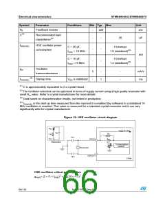
Figure 19: HSE oscillator circuit diagram
R
m
f
to core
HSE
C
O
R
g
L
m
F
C
L1
C
m
OSCIN
m
Resonator
Consumption
control
Resonator
OSCOUT
C
L2
STM8
HSE oscillator critical g m equation
gmcrit= (2 × Π × fHSE)2 × Rm(2Co + C)2
66/116
DocID15590 Rev 8

 STMICROELECTRONICS [ ST ]