STM8S903K3 STM8S903F3
Electrical characteristics
10.3.3
External clock sources and timing characteristics
HSE user external clock
Subject to general operating conditions for VDD and TA.
Table 34: HSE user external clock characteristics
Symbol
Parameter
Conditions
Min
Max
Unit
MHz
fHSE_ext
User external clock source
frequency
0
16
(1)
VHSEH
OSCIN input pin high level
voltage
0.7 x VDD
VDD + 0.3 V
V
(1)
VHSEL
ILEAK_HSE
(1) Data based on characterization results, not tested in production.
OSCIN input pin low level
voltage
VSS
-1
0.3 x VDD
+1
OSCIN input leakage current VSS < VIN < VDD
μA
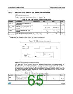
Figure 18: HSE external clocksource
V
V
HSEH
HSEL
f
HSE
External clock
source
OSCIN
STM8
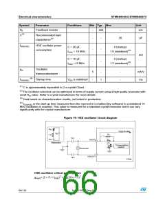
HSE crystal/ceramic resonator oscillator
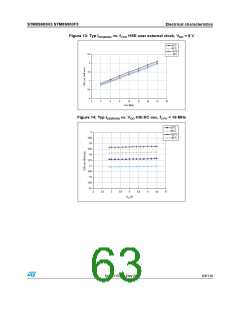
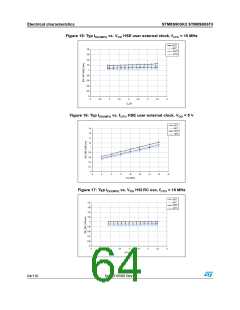
The HSE clock can be supplied with a 1 to 16 MHz crystal/ceramic resonator oscillator. All
the information given in this paragraph is based on characterization results with specified
typical external components. In the application, the resonator and the load capacitors have
to be placed as close as possible to the oscillator pins in order to minimize output distortion
and start-up stabilization time. Refer to the crystal resonator manufacturer for more details
(frequency, package, accuracy...).
Table 35: HSE oscillator characteristics
Symbol
Parameter
Conditions
Min Typ Max
Unit
MHz
fHSE
External high speed
oscillator frequency
1
-
16
DocID15590 Rev 8
65/116

 STMICROELECTRONICS [ ST ]