Electrical characteristics
STM8S903K3 STM8S903F3
HSI internal RC/fCPU = fMASTER = 16 MHz, VDD = 5 V
Table 33: Peripheral current consumption
Parameter Typ.
Symbol
Unit
µA
IDD(TIM1)
TIM1 supply current(1)
210
130
50
IDD(TIM5)
IDD(TIM6)
IDD(UART1)
TIM5 supply current(1)
TIM6 timer supply current(1)
UART1 supply current(2)
SPI supply current(2)
120
45
IDD(SPI)
2
IDD(I
I2C supply current(2)
65
C)
IDD(ADC1)
ADC1 supply current when converting(3)
1000
(1) Data based on a differential IDD measurement between reset configuration and timer
counter running at 16 MHz. No IC/OC programmed (no I/O pads toggling). Not tested in
production.
(2) Data based on a differential IDD measurement between the on-chip peripheral when kept
under reset and not clocked and the on-chip peripheral when clocked and not kept under
reset. No I/O pads toggling. Not tested in production.
(3) Data based on a differential IDD measurement between reset configuration and continuous
A/D conversions. Not tested in production.
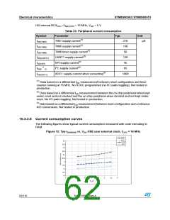
10.3.2.8 Current consumption curves
The following figures show typical current consumption measured with code executing in
RAM.
Figure 12: Typ IDD(RUN) vs. VDD HSE user external clock, fCPU = 16 MHz
62/116
DocID15590 Rev 8

 STMICROELECTRONICS [ ST ]