Electrical characteristics
STM32F105xx, STM32F107xx
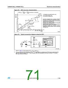
General PCB design guidelines
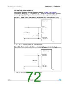
Power supply decoupling should be performed as shown in Figure 31 or Figure 32,
depending on whether V is connected to V or not. The 10 nF capacitors should be
ceramic (good quality). They should be placed them as close as possible to the chip.
REF+
DDA
Figure 31. Power supply and reference decoupling (V
not connected to V
)
DDA
REF+
STM32F10xxx
V
REF+
(See note 1)
1 µF // 10 nF
V
V
DDA
1 µF // 10 nF
/V
SSA REF-
(See note 1)
ai14380c
1. VREF+ and VREF– inputs are available only on 100-pin packages.
Figure 32. Power supply and reference decoupling (V
connected to V
)
REF+
DDA
STM32F10xxx
VREF+/VDDA
(See note 1)
1 µF // 10 nF
VREF–/VSSA
(See note 1)
ai14381c
1. VREF+ and VREF– inputs are available only on 100-pin packages.
72/95
Doc ID 15274 Rev 4

 STMICROELECTRONICS [ ST ]