STM32F405xx, STM32F407xx
Electrical characteristics
(1)
Table 32. LSE oscillator characteristics (fLSE = 32.768 kHz)
Symbol
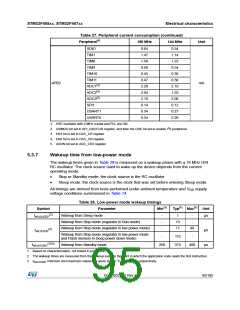
Parameter
Feedback resistor
Conditions
Min
Typ
Max
Unit
RF
IDD
gm
-
-
18.4
-
1
-
MΩ
µA
LSE current consumption
Oscillator Transconductance
startup time
-
-
2.8
-
µA/V
s
(2)
tSU(LSE)
VDD is stabilized
2
-
1. Guaranteed by design, not tested in production.
2. tSU(LSE) is the startup time measured from the moment it is enabled (by software) to a stabilized
32.768 kHz oscillation is reached. This value is measured for a standard crystal resonator and it can vary
significantly with the crystal manufacturer
Note:
For information on electing the crystal, refer to the application note AN2867 “Oscillator
design guide for ST microcontrollers” available from the ST website www.st.com.
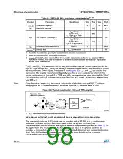
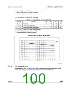
Figure 33. Typical application with a 32.768 kHz crystal
Resonator with
integrated capacitors
C
L1
f
OSC32_IN
LSE
Bias
controlled
gain
32.768 kHz
resonator
R
F
STM32F
OSC32_OUT
C
L2
ai17531
5.3.9
Internal clock source characteristics
The parameters given in Table 33 and Table 34 are derived from tests performed under
ambient temperature and V supply voltage conditions summarized in Table 14.
DD
High-speed internal (HSI) RC oscillator
(1)
Table 33. HSI oscillator characteristics
Symbol
Parameter
Frequency
Conditions
Min
Typ
Max Unit
fHSI
-
16
-
MHz
%
User-trimmed with the RCC_CR
register
-
-
-
1
TA = –40 to
Accuracy of the HSI
oscillator
–8
4.5
%
105 °C(2)
ACCHSI
Factory-
calibrated
TA = –10 to 85 °C(2) –4
-
-
4
1
%
%
TA = 25 °C
–1
-
HSI oscillator
startup time
(3)
tsu(HSI)
2.2
60
4
µs
HSI oscillator
power consumption
IDD(HSI)
-
80
µA
DocID022152 Rev 4
99/185

 STMICROELECTRONICS [ ST ]