Electrical characteristics
STM32F405xx, STM32F407xx
Table 36. PLLI2S (audio PLL) characteristics (continued)
Symbol
Parameter
Conditions
Min
Typ
Max
Unit
ps
RMS
-
90
-
Cycle to cycle at
12.288 MHz on
48KHz period,
N=432, R=5
peak
to
peak
-
280
-
Master I2S clock jitter
Average frequency of
12.288 MHz
Jitter(3)
-
-
90
-
-
ps
N = 432, R = 5
on 1000 samples
Cycle to cycle at 48 KHz
on 1000 samples
WS I2S clock jitter
400
ps
VCO freq = 192 MHz
VCO freq = 432 MHz
0.15
0.45
0.40
0.75
PLLI2S power consumption on
VDD
(4)
IDD(PLLI2S)
-
-
mA
mA
VCO freq = 192 MHz
VCO freq = 432 MHz
0.30
0.55
0.40
0.85
PLLI2S power consumption on
VDDA
(4)
IDDA(PLLI2S)
1. Take care of using the appropriate division factor M to have the specified PLL input clock values.
2. Guaranteed by design, not tested in production.
3. Value given with main PLL running.
4. Based on characterization, not tested in production.
5.3.11
PLL spread spectrum clock generation (SSCG) characteristics
The spread spectrum clock generation (SSCG) feature allows to reduce electromagnetic
interferences (see Table 43: EMI characteristics). It is available only on the main PLL.
Table 37. SSCG parameters constraint
Symbol
Parameter
Min
Typ
Max(1)
Unit
fMod
md
Modulation frequency
Peak modulation depth
-
0.25
-
-
-
-
10
2
KHz
%
MODEPER * INCSTEP
2
15−1
-
1. Guaranteed by design, not tested in production.
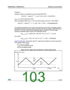
Equation 1
The frequency modulation period (MODEPER) is given by the equation below:
MODEPER = round[fPLL_IN ⁄ (4 × fMod)]
f
and f
must be expressed in Hz.
PLL_IN
Mod
As an example:
If f = 1 MHz, and f
= 1 kHz, the modulation depth (MODEPER) is given by
MOD
PLL_IN
equation 1:
MODEPER = round[106 ⁄ (4 × 10³)] = 250
102/185
DocID022152 Rev 4

 STMICROELECTRONICS [ ST ]