STM32F405xx, STM32F407xx
Electrical characteristics
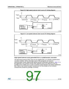
Figure 30. High-speed external clock source AC timing diagram
V
HSEH
90%
10%
V
HSEL
t
t
t
W(HSE)
t
t
W(HSE)
r(HSE)
f(HSE)
T
HSE
f
HSE_ext
External
I
L
OSC _I N
clock source
STM32F
ai17528
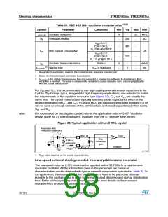
Figure 31. Low-speed external clock source AC timing diagram
V
LSEH
90%
10%
V
LSEL
t
t
t
W(LSE)
t
t
W(LSE)
r(LSE)
f(LSE)
T
LSE
f
LSE_ext
External
I
L
OSC32_IN
clock source
STM32F
ai17529
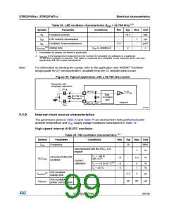
High-speed external clock generated from a crystal/ceramic resonator
The high-speed external (HSE) clock can be supplied with a 4 to 26 MHz crystal/ceramic
resonator oscillator. All the information given in this paragraph are based on
characterization results obtained with typical external components specified in Table 31. In
the application, the resonator and the load capacitors have to be placed as close as
possible to the oscillator pins in order to minimize output distortion and startup stabilization
time. Refer to the crystal resonator manufacturer for more details on the resonator
characteristics (frequency, package, accuracy).
DocID022152 Rev 4
97/185

 STMICROELECTRONICS [ ST ]