STM32F405xx, STM32F407xx
Electrical characteristics
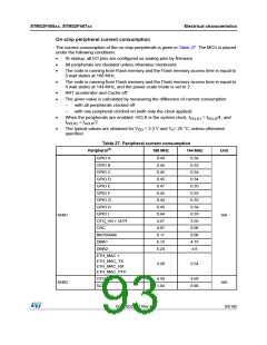
On-chip peripheral current consumption
The current consumption of the on-chip peripherals is given in Table 27. The MCU is placed
under the following conditions:
•
•
•
At startup, all I/O pins are configured as analog pins by firmware.
All peripherals are disabled unless otherwise mentioned
The code is running from Flash memory and the Flash memory access time is equal to
5 wait states at 168 MHz.
•
The code is running from Flash memory and the Flash memory access time is equal to
4 wait states at 144 MHz, and the power scale mode is set to 2.
•
•
ART accelerator and Cache off.
The given value is calculated by measuring the difference of current consumption
–
–
with all peripherals clocked off
with one peripheral clocked on (with only the clock applied)
•
•
When the peripherals are enabled: HCLK is the system clock, f
= f
/4, and
PCLK1
HCLK
f
= f
/2.
PCLK2
HCLK
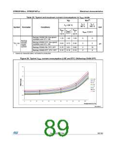
The typical values are obtained for V = 3.3 V and T = 25 °C, unless otherwise
DD
A
specified.
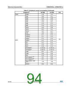
Table 27. Peripheral current consumption
Peripheral(1)
168 MHz
144 MHz
Unit
GPIO A
GPIO B
GPIO C
GPIO D
GPIO E
GPIO F
GPIO G
GPIO H
GPIO I
0.49
0.45
0.45
0.45
0.47
0.45
0.44
0.45
0.44
4.57
0.07
0.11
6.15
6.24
0.36
0.33
0.34
0.34
0.35
0.33
0.33
0.34
0.33
3.55
0.06
0.08
4.75
4.8
AHB1
mA
OTG_HS + ULPI
CRC
BKPSRAM
DMA1
DMA2
ETH_MAC +
ETH_MAC_TX
ETH_MAC_RX
ETH_MAC_PTP
3.28
2.54
OTG_FS
DCMI
4.59
1.04
3.69
0.80
AHB2
mA
DocID022152 Rev 4
93/185

 STMICROELECTRONICS [ ST ]