Electrical characteristics
STM32F405xx, STM32F407xx
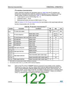
(1)(2)
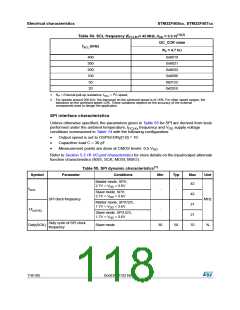
Table 54. SCL frequency (f
fSCL (kHz)
= 42 MHz.,VDD = 3.3 V)
PCLK1
I2C_CCR value
RP = 4.7 kΩ
400
300
200
100
50
0x8019
0x8021
0x8032
0x0096
0x012C
0x02EE
20
1. RP = External pull-up resistance, fSCL = I2C speed,
2. For speeds around 200 kHz, the tolerance on the achieved speed is of 5%. For other speed ranges, the
tolerance on the achieved speed 2%. These variations depend on the accuracy of the external
components used to design the application.
SPI interface characteristics
Unless otherwise specified, the parameters given in Table 55 for SPI are derived from tests
performed under the ambient temperature, f
frequency and V supply voltage
PCLKx
DD
conditions summarized in Table 14 with the following configuration:
•
•
•
Output speed is set to OSPEEDRy[1:0] = 10
Capacitive load C = 30 pF
Measurement points are done at CMOS levels: 0.5 V
DD
Refer to Section 5.3.16: I/O port characteristics for more details on the input/output alternate
function characteristics (NSS, SCK, MOSI, MISO).
(1)
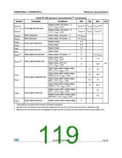
Table 55. SPI dynamic characteristics
Symbol
Parameter
Conditions
Min
Typ
Max
Unit
Master mode, SPI1,
2.7V < VDD < 3.6V
42
fSCK
-
-
Slave mode, SPI1,
2.7V < VDD < 3.6V
42
21
21
70
SPI clock frequency
MHz
Master mode, SPI1/2/3,
1.7V < VDD < 3.6V
1/tc(SCK)
-
-
Slave mode, SPI1/2/3,
1.7V < VDD < 3.6V
Duty cycle of SPI clock
frequency
Duty(SCK)
Slave mode
30
50
%
118/185
DocID022152 Rev 4

 STMICROELECTRONICS [ ST ]