STM32F405xx, STM32F407xx
Electrical characteristics
2
Table 53. I C characteristics (continued)
Standard mode I2C(1) Fast mode I2C(1)(2)
Symbol
Parameter
Unit
Min
Max
Min
Max
th(STA)
tsu(STA)
Start condition hold time
4.0
-
0.6
-
µs
Repeated Start condition
setup time
4.7
4.0
4.7
-
-
-
0.6
0.6
1.3
-
-
-
tsu(STO)
Stop condition setup time
μs
μs
Stop to Start condition time
(bus free)
tw(STO:STA)
Capacitive load for each bus
line
Cb
-
400
-
400
pF
Guaranteed by design, not tested in production.
1.
2. fPCLK1 must be at least 2 MHz to achieve standard mode I2C frequencies. It must be at least 4 MHz to
achieve fast mode I2C frequencies, and a multiple of 10 MHz to reach the 400 kHz maximum I2C fast mode
clock.
3. The device must internally provide a hold time of at least 300 ns for the SDA signal in order to bridge the
undefined region of the falling edge of SCL.
4. The maximum data hold time has only to be met if the interface does not stretch the low period of SCL
signal.
2
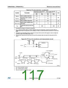
Figure 39. I C bus AC waveforms and measurement circuit
V
V
DD_I2C
DD_I2C
STM32Fxx
RP
RP
RS
RS
SDA
SCL
I²C bus
S TAR T REPEATED
S TAR T
S TAR T
t
su(STA)
S D A
t
t
t
su(SDA)
r(SDA)
f(SDA)
t
w(STO:STA)
S TOP
t
t
h(STA)
t
w(SCLL)
h(SDA)
SCL
t
t
t
su(STO)
r(SCL)
t
w(SCLH)
f(SCL)
ai14979c
1. Rs= series protection resistor.
2. Rp = external pull-up resistor.
3. VDD_I2C is the I2C bus power supply.
DocID022152 Rev 4
117/185

 STMICROELECTRONICS [ ST ]