ST92F124/F150/F250 - ELECTRICAL CHARACTERISTICS
EXTERNAL INTERRUPT TIMING TABLE
(V = 5V ± 10%, T = –40°C to +125°C, C
= 50pF, f = 24MHz, unless otherwise specified)
INTCLK
DD
N°
A
Load
Value
Unit
Symbol
Parameter
Formula
≥Tck+10
≥Tck+10
≥Tck+10
≥Tck+10
Min
50
1
2
3
4
TwINTLR
TwINTHR
TwINTHF
TwINTLF
Low Level Minimum Pulse Width in Rising Edge Mode
High Level Minimum Pulse Width in Rising Edge Mode
High Level Minimum Pulse Width in Falling Edge Mode
Low Level Minimum Pulse Width in Falling Edge Mode
ns
ns
ns
ns
50
50
50
Note:
The value in the left hand column shows the formula used to calculate the timing minimum or maximum from the oscillator clock period.
The value in the right hand two columns shows the timing minimum and maximum for an internal clock at 24MHz (INTCLK).
Measurement points are V for positive pulses and V for negative pulses.
IH
IL
Legend:
Tck = INTCLK period = Crystal Oscillator Clock period when CLOCK1 is not divided by 2;
2 x Crystal Oscillator Clock period when CLOCK1 7is divided by 2;
Crystal Oscillator Clock period x PLL factor when the PLL is enabled.
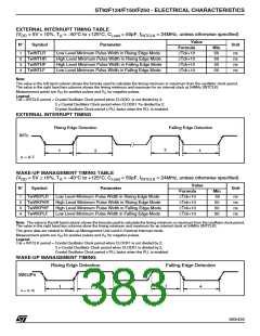
EXTERNAL INTERRUPT TIMING
Rising Edge Detection
INTn
Falling Edge Detection
n = 0-7
WAKE-UP MANAGEMENT TIMING TABLE
(V = 5V ± 10%, T = –40°C to +125°C, C
= 50pF, f = 24MHz, unless otherwise specified)
INTCLK
DD
A
Load
Value
Unit
N°
Symbol
Parameter
Formula
≥Tck+10
≥Tck+10
≥Tck+10
≥Tck+10
Min
50
1
2
3
4
TwWKPLR
TwWKPHR
TwWKPHF
TwWKPLF
Low Level Minimum Pulse Width in Rising Edge Mode
High Level Minimum Pulse Width in Rising Edge Mode
High Level Minimum Pulse Width in Falling Edge Mode
Low Level Minimum Pulse Width in Falling Edge Mode
ns
ns
ns
ns
50
50
50
Note: The value in the left hand column shows the formula used to calculate the timing minimum or maximum from the oscillator clock period.
The value in the right hand two columns show the timing minimum and maximum for an internal clock at 24MHz (INTCLK).
The given data are related to Wake-up Management Unit used in External Interrupt mode.
Measurement points are V for positive pulses and V for negative pulses.
IH
IL
Legend:
Tck = INTCLK period = Crystal Oscillator Clock period when CLOCK1 is not divided by 2;
2 x Crystal Oscillator Clock period when CLOCK1 is divided by 2;
Crystal Oscillator Clock period x PLL factor when the PLL is enabled.
WAKE-UP MANAGEMENT TIMING
Rising Edge Detection
Falling Edge Detection
WKUPn
n = 0-15
383/426
1

 STMICROELECTRONICS [ ST ]