10-BIT ANALOG TO DIGITAL CONVERTER (ADC)
REGISTER DESCRIPTION (Cont’d)
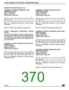
CHANNEL B LOWER THRESHOLD LOW
REGISTER (LTBLR)
CHANNEL A UPPER THRESHOLD LOW
REGISTER (UTALR)
R249 - Read/Write
Register Page: 63
R247 - Read/Write
Register Page: 63
Reset Value: xx00 0000
Reset Value: xx00 0000
7
0
0
7
0
0
LTB.1 LTB.0
0
0
0
0
0
UTA.1 UTA.0
0
0
0
0
0
Bits 7:6 = LTB.[1:0]: Channel B [1:0] bit Lower
Threshold
Bits 7:6 = UTA.[1:0]: Channel A [1:0] bit Upper
Threshold
Bits 5:0 = Reserved, forced by hardware to 0.
Bits 5:0 = Reserved, forced by hardware to 0.
UPPER THRESHOLD REGISTERS (UTiHR/
UTiLR)
CHANNEL B UPPER THRESHOLD HIGH REG-
ISTER (UTBHR)
R250 - Read/Write
The two pairs of Upper Threshold High/Low Reg-
isters are used to store the user programmable up-
per threshold 10-bit values, to be compared with
the current conversion results, thus setting the up-
per window limit.
Register Page: 63
Reset Value: undefined
7
0
UTB.9 UTB.8 UTB.7 UTB.6 UTB.5 UTB.4 UTB.3 UTB.2
CHANNEL A UPPER THRESHOLD HIGH REG-
ISTER (UTAR)
Bits 7:0 = UTB.[9:2]: Channel B [9:2] bit Upper
Threshold
R248 - Read/Write
Register Page: 63
Reset Value: undefined
CHANNEL B UPPER THRESHOLD LOW
REGISTER (UTBLR)
7
0
R251 - Read/Write
UTA.9 UTA.8 UTA.7 UTA.6 UTA.5 UTA.4 UTA.3 UTA.2
Register Page: 63
Reset Value: xx00 0000
Bits 7:0 = UTA.[9:2]: Channel 6 [9:2] bit Upper
Threshold value
7
0
0
UTB.1 UTB.0
0
0
0
0
0
Bits 7:6 = UTB.[1:0]: Channel B [1:0] bit Lower
Threshold
Bits 5:0 = Reserved, forced by hardware to 0.
370/426
9

 STMICROELECTRONICS [ ST ]