10-BIT ANALOG TO DIGITAL CONVERTER (ADC)
ANALOG TO DIGITAL CONVERTER (Cont’d)
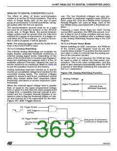
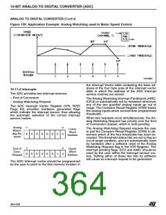
Figure 158. Application Example: Analog Watchdog used in Motor Speed Control
the Interrupt Vector table containing the base ad-
dress of the four byte area of the interrupt vector
table in which the address of the ADC interrupt
service routines are stored.
10.11.4 Interrupts
The ADC provides two interrupt sources:
– End of Conversion
The Analog Watchdog Interrupt Pending bit (AWD,
ICR.6) is automatically set by hardware whenever
any of the two guarded analog inputs go out of
range. The Compare Result Register (CRR) tracks
the analog inputs which exceed their programmed
thresholds.
– Analog Watchdog Request
The ADC Interrupt Vector Register (IVR, R255
Page 63) provides hardware generated flags
which indicate the interrupt source, thus allowing
the automatic selection of the correct interrupt
service routine.
When two requests occur simultaneously, the An-
alog Watchdog Request has priority over the End
of Conversion request, which is held pending.
Analog
Watch-
dog Re-
quest
7
0
0
The Analog Watchdog Request requires the user
to poll the Compare Result Register (CRR) to de-
termine which of the four thresholds has been ex-
ceeded. The threshold status bits are set to flag an
out of range condition, and are automatically reset
by hardware after a software reset of the Analog
Watchdog Request flag in the ICR Register. The
interrupt pending flags, ECV and AWD, should be
reset by the user within the interrupt service rou-
tine. Setting either of these two bits by software
will cause an interrupt request to be generated.
Lower
Word
Address
X
X
X
X
X
X
0
7
0
0
End of
Conv.
Request
Upper
Word
Address
X
X
X
X
X
X
1
The ADC Interrupt vector should be programmed
by the user to point to the first memory location in
364/426
9

 STMICROELECTRONICS [ ST ]