10-BIT ANALOG TO DIGITAL CONVERTER (ADC)
10.11 10-BIT ANALOG TO DIGITAL CONVERTER (ADC)
10.11.1 Main Characteristics
■ 10-bit Resolution
The conversion time depends on the INTCLK fre-
quency and the prescaler factor stored in the
PR[2:0] bits of the CLR2 register (R253-page 63)).
■ Monotonicity: Guaranteed
■ No missing codes: Guaranteed
■ 3-bit INTCLK/2 Frequency Prescaler
■ Internal/External Trigger availability
■ Continuous/Single Modes
■ Autoscan Mode
AV
and AV are the high and low level refer-
SS
DD
ence voltage pins. Up to 16 multiplexed Analog In-
puts are available depending on the specific de-
vice type. With the AUTOSCAN feature, a group of
signals can be converted sequentially by simply
programming the starting address of the first ana-
log channel to be converted.
■ Power Down Mode
■ 16 10-bit data registers (two per channel)
There are two Analog Watchdogs used for the
continuous hardware monitoring of two consecu-
tive input channels selectable by means of the
CC[3:0] bits in the CLR1 register (R252-page 63).
An Interrupt request is generated whenever the
converted value of either of these two analog in-
puts exceeds the upper or lower programmed
threshold values.
■ Two analog watchdogs selectable on adjacent
channels
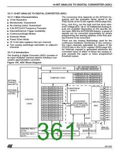
10.11.2 Introduction
The Analog to Digital Converter (ADC) consists of
an input multiplex channel selector feeding a suc-
cessive approximation converter.
Figure 155. ADC Block Diagram
INT. VECTOR POINTER
INT. CONTROL REGISTER
INTERRUPT UNIT
COMPARE RESULT REGISTER
THRESHOLD H/L REGISTER BU
THRESHOLD H/L REGISTER BL
THRESHOLD H/L REGISTER AH
THRESHOLD H/L REGISTER AL
COMPARE LOGIC
INTERNAL
TRIGGER
(from MFT0)
AIN 15
AIN 14
AIN 13
AIN 12
AIN 11
DATA REGISTER H/L15
DATA REGISTER H/L14
DATA REGISTER H/L13
DATA REGISTER H/L12
DATA REGISTER H/L11
DATA REGISTER H/L10
DATA REGISTER H/L 9
DATA REGISTER H/L 8
DATA REGISTER H/L 7
DATA REGISTER H/L 6
DATA REGISTER H/L 5
DATA REGISTER H/L 4
DATA REGISTER H/L 3
DATA REGISTER H/L 2
DATA REGISTER H/L 1
DATA REGISTER H/L 0
CONVERSION
RESULT
EXTERNAL
TRIGGER
(EXTRG)
AIN 10
AIN 9
AIN 8
CONTROL
LOGIC
SUCCESSIVE
ANALOG
MUX
APPROXIMATION
ANALOG TO DIGITAL
CONVERTER
AIN 7
AIN 6
AIN 5
AIN 4
AIN 3
10 bit
AIN 2
AIN 1
AIN 0
CKAD
CK PRESCALER
ANALOG
SECTION
CONTROL REG.2
(CLR2)
DIVIDER by 2
AUTOSCAN LOGIC
CONTROL REG.1
(CLR1)
INTCLK
361/426
9

 STMICROELECTRONICS [ ST ]