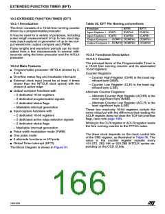
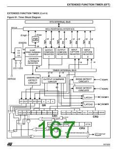
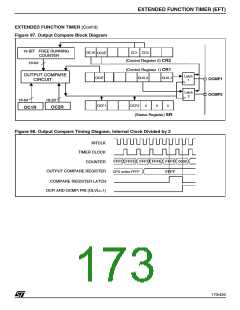
EXTENDED FUNCTION TIMER (EFT)
EXTENDED FUNCTION TIMER (Cont’d)
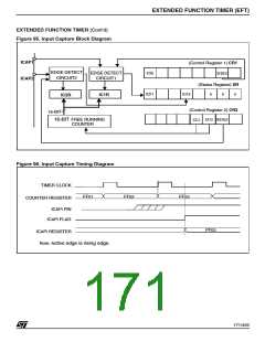
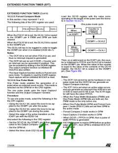
10.3.3.3 Input Capture
– Select the edge of the active transition on the
ICAP1 pin with the IEDG1 bit if ICAP1 is active.
In this section, the index, i, may be 1 or 2.
When an input capture occurs:
The two input capture 16-bit registers (IC1R and
IC2R) are used to latch the value of the free run-
ning counter after a transition detected by the
ICAPi pin (see figure 5).
– ICFi bit is set.
– The ICiR register contains the value of the free
running counter on the active transition on the
ICAPi pin (see Figure 96).
MS Byte
LS Byte
– A timer interrupt is generated under the following
two conditions :
ICiR
ICiHR
ICiLR
1. If the ICIE bit (for both ICAP1 & ICAP2) and
the EFTIS bit are set.
ICi Rregister is a read-only register.
Note: If the ICIE bit is set, the status of the
IC1IE/IC2IE bits in the CR3 register is not sig-
nificant.
The active transition is software programmable
through the IEDGi bit of the Control Register (CRi).
2. If the ICIE bit is reset and the IC1IE and /or
IC2IE bits are set and the EFTIS bit is set.
Timing resolution is one count of the free running
counter: (INTCLK
).
/CC[1:0]
Otherwise, the interrupt remains pending until
the related enable bits are set.
Procedure
To use the input capture function select the follow-
ing in the CR2 register:
Clearing the Input Capture interrupt request is
done by:
– Select the timer clock (CC[1:0] (see Table 36).
1. An access (read or write) to the SR register
– Select the edge of the active transition on the
ICAP2 pin with the IEDG2 bit, if ICAP2 is active.
while the ICFi bit is set.
2. An access (read or write) to the ICiLR register.
And select the following in the CR1/CR3 register:
– To enable both ICAP1 & ICAP2 interrupts, set
the ICIE bit in the CR1 register (in this case, the
IC1IE & IC2IE enable bits are not significant).
To enable only one ICAP interrupt, reset the ICIE
bit and set the IC1IE (or IC2IE) bit.
Note: If ICIE is reset and both IC1IE & IC2IE are
set, both interrupts are enabled.
Note: After reading the ICiHR register, transfer of
input capture data is inhibited until the ICiLR regis-
ter is also read.
The ICiR register always contains the free running
counter value which corresponds to the most re-
cent input capture.
In all cases, set the EFTIS bit to enable timer in-
terrupts globally
170/426
9

 STMICROELECTRONICS [ ST ]