ST10F276E
Electrical characteristics
6. This specification is only valid during Reset, or during Hold- or Adapt-mode. Port 6 pins are only affected if they are used
for CS output and the open drain function is not enabled.
7. The maximum current may be drawn while the respective signal line remains inactive.
8. The minimum current must be drawn in order to drive the respective signal line active.
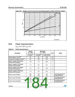
9. The power supply current is a function of the operating frequency (f
is expressed in MHz). This dependency is
CPU
illustrated in Figure 45 below. This parameter is tested at V
and at maximum CPU clock frequency with all outputs
DDmax
disconnected and all inputs at V or V , RSTIN pin at V : This implies I/O current is not considered. The device is
IH1min
IL
IH
doing the following:
- Fetching code from IRAM and XRAM1, accessing in read and write to both XRAM modules
- Watchdog Timer is enabled and regularly serviced
- RTC is running with main oscillator clock as reference, generating a tick interrupts every 192 clock cycles
- Four channels of XPWM are running (waves period: 2, 2.5, 3 and 4 CPU clock cycles): No output toggling
- Five General Purpose Timers are running in timer mode with prescaler equal to 8 (T2, T3, T4, T5, T6)
- ADC is in Auto Scan Continuous Conversion mode on all 16 channels of Port5
- All interrupts generated by XPWM, RTC, Timers and ADC are not serviced
10. The power supply current is a function of the operating frequency (f
is expressed in MHz). This dependency is
CPU
illustrated in Figure 45 below. This parameter is tested at V
and at maximum CPU clock frequency with all outputs
DDmax
disconnected and all inputs at V or V , RSTIN pin at V : This implies I/O current is not considered. The device is
IH1min
IL
IH
doing the following:
- Fetching code from all sectors of both IFlash and XFlash, accessing in read (few fetches) and write to XRAM
- Watchdog Timer is enabled and regularly serviced
- RTC is running with main oscillator clock as reference, generating a tick interrupts every 192 clock cycles
- Four channels of XPWM are running (waves period: 2, 2.5, 3 and 4 CPU clock cycles): No output toggling
- Five General Purpose Timers are running in timer mode with prescaler equal to 8 (T2, T3, T4, T5, T6)
- ADC is in Auto Scan Continuous Conversion mode on all 16 channels of Port5
- All interrupts generated by XPWM, RTC, Timers and ADC are not serviced
11. The Idle mode supply current is a function of the operating frequency (f
is expressed in MHz). This dependency is
CPU
illustrated in Figure 44 below. These parameters are tested and at maximum CPU clock with all outputs disconnected and
all inputs at V or V , RSTIN pin at V
.
IH1min
IL
IH
12. This parameter is tested including leakage currents. All inputs (including pins configured as inputs) at 0 to 0.1V or at V
-
DD
0.1V to V , V
= 0V, all outputs (including pins configured as outputs) disconnected. Furthermore, the Main Voltage
DD
AREF
Regulator is assumed off: In case it is not, additional 1mA shall be assumed.
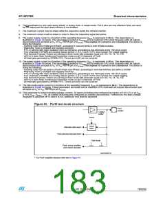
Figure 44. Port2 test mode structure
0ꢁꢌꢉ
##ꢉ)/
/UTPUT
BUFFER
#LOCK
)NPUT
!LTERNATE DATA INPUT
LATCH
&AST EXTERNAL INTERRUPT INPUT
4EST MODE
&LASH SENSE AMPLIFIER
AND COLUMN DECODER
'!0'2)ꢉꢉꢀꢁꢀ
1 For Port2 complete structure refer also to Figure 44.
Doc ID 12303 Rev 3
183/235

 STMICROELECTRONICS [ ST ]