ST10F276E
System reset
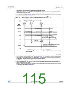
5 V operation), the asynchronous reset is then immediately entered.
3. RSTIN pin is pulled low if bit BDRSTEN (bit 3 of SYSCON register) was previously set by software. Bit
BDRSTEN is cleared after reset.
4. Minimum RSTIN low pulse duration shall also be longer than 500ns to guarantee the pulse is not masked
by the internal filter (refer to Section 19.1).
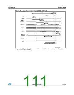
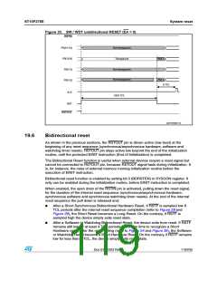
Figure 29. Synchronous short / long hardware RESET (EA = 0)
ꢍꢃꢏ
dꢁ 4#, dꢀꢁ 4#,
ꢘ ꢀꢉꢈꢁ 4#,
234).
ꢍꢀꢏ
ꢍꢇꢏ
t ꢃꢉ NS
ꢀꢃꢉꢉ NS
tꢀꢃꢉ NS
ꢀꢃꢉꢉ NS
t ꢃꢉ NS
ꢀꢃꢉꢉ NS
234&
ꢍAFTER FILTERꢏ
0ꢉ;ꢀꢃꢐꢀꢈ=
.OT TRANSPARENT
0ꢉ;ꢀꢁꢐꢁ=
0ꢉ;ꢀꢐꢉ=
.OT Tꢌ
4RANSPARENT
.OT Tꢌ
.OT Tꢌ
.OT TRANSPARENT
ꢍꢈꢏ
ꢈꢌꢌꢆ 4#,
ꢆ 4#,
!,%
ꢀꢉꢁꢇ 4#,
ꢆ 4#,
234
!T THIS TIME 234& IS SAMPLED ()'( OR ,/7
SO IT IS 3(/24 OR ,/.' RESET
234/54
20$
ꢍꢁꢏ
6
ꢔ ꢁꢌꢃ 6 ASYNCHRONOUS RESET NOT ENTERED
'!0'2)ꢉꢉꢀꢉꢄ
20$
ꢁꢉꢉ ! DISCHARGE
1. RSTIN assertion can be released there. Refer also to Section 19.1 for details on minimum pulse duration.
2. If during the reset condition (RSTIN low), RPD voltage drops below the threshold voltage (about 2.5V for
5V operation), the asynchronous reset is then immediately entered.
3. 3 to 8 TCL depending on clock source selection.
4. RSTIN pin is pulled low if bit BDRSTEN (bit 3 of SYSCON register) was previously set by software. Bit
BDRSTEN is cleared after reset.
5. Minimum RSTIN low pulse duration shall also be longer than 500ns to guarantee the pulse is not masked
by the internal filter (refer to Section 19.1).
Doc ID 12303 Rev 3
115/235

 STMICROELECTRONICS [ ST ]